
Roller press having torque balance

a technology of torque balance and roller press, which is applied in the field of roller press, can solve the problems of complex logistic and possible handling of the machine frame, and achieve the effect of producing more easily and more cost-effectively

Inactive Publication Date: 2015-08-18
KHD HUMBOLDT WEDAG GMBH
View PDF9 Cites 1 Cited by
  • Summary
  • Abstract
  • Description
  • Claims
  • Application Information

AI Technical Summary

Benefits of technology

[0006]The object of the invention is therefore to refine the roller presses such that the centering is designed such that it can be produced more easily and more cost-effectively, while maintaining the system of forces which is self-contained and is largely separate from the machine frame.
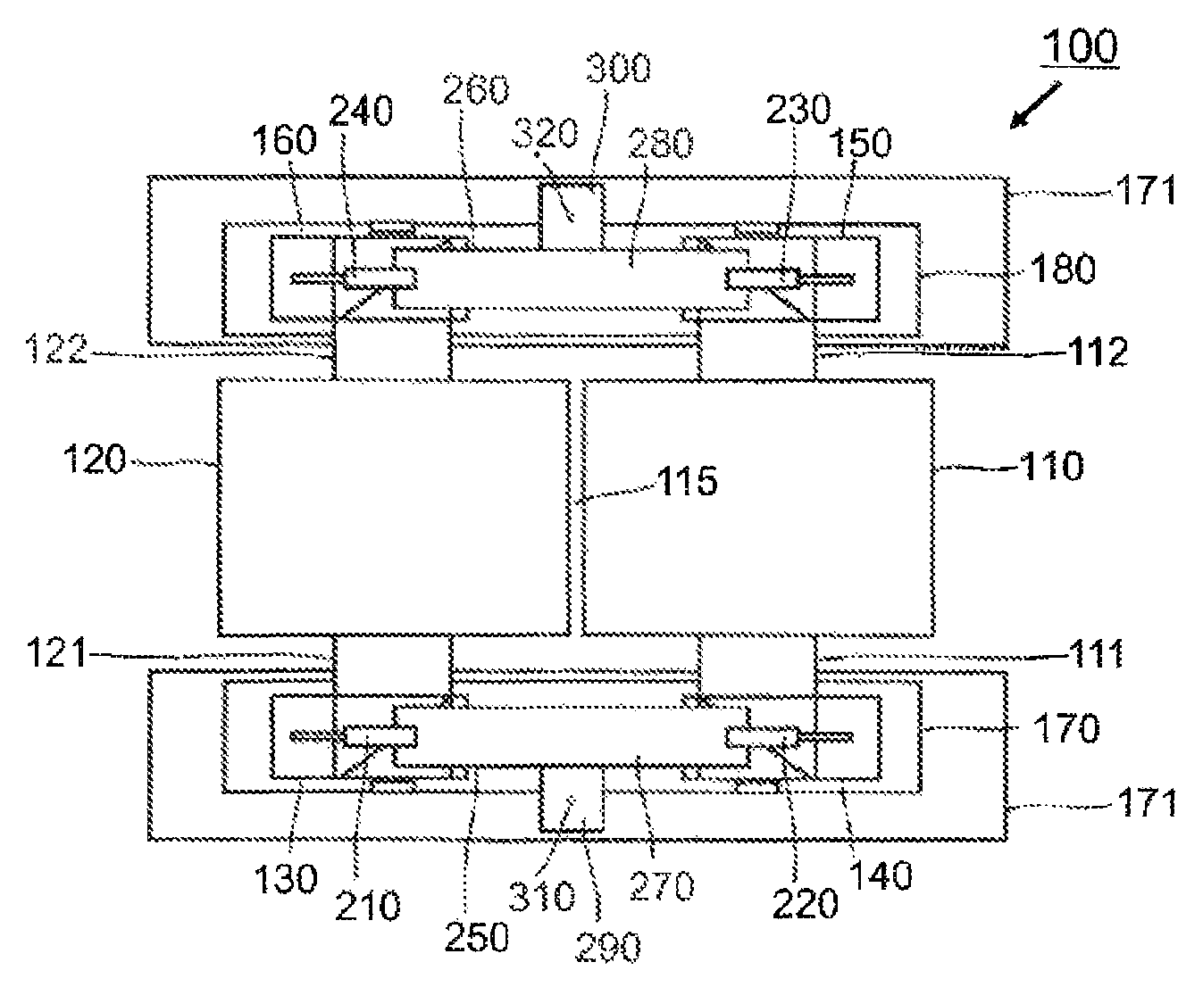
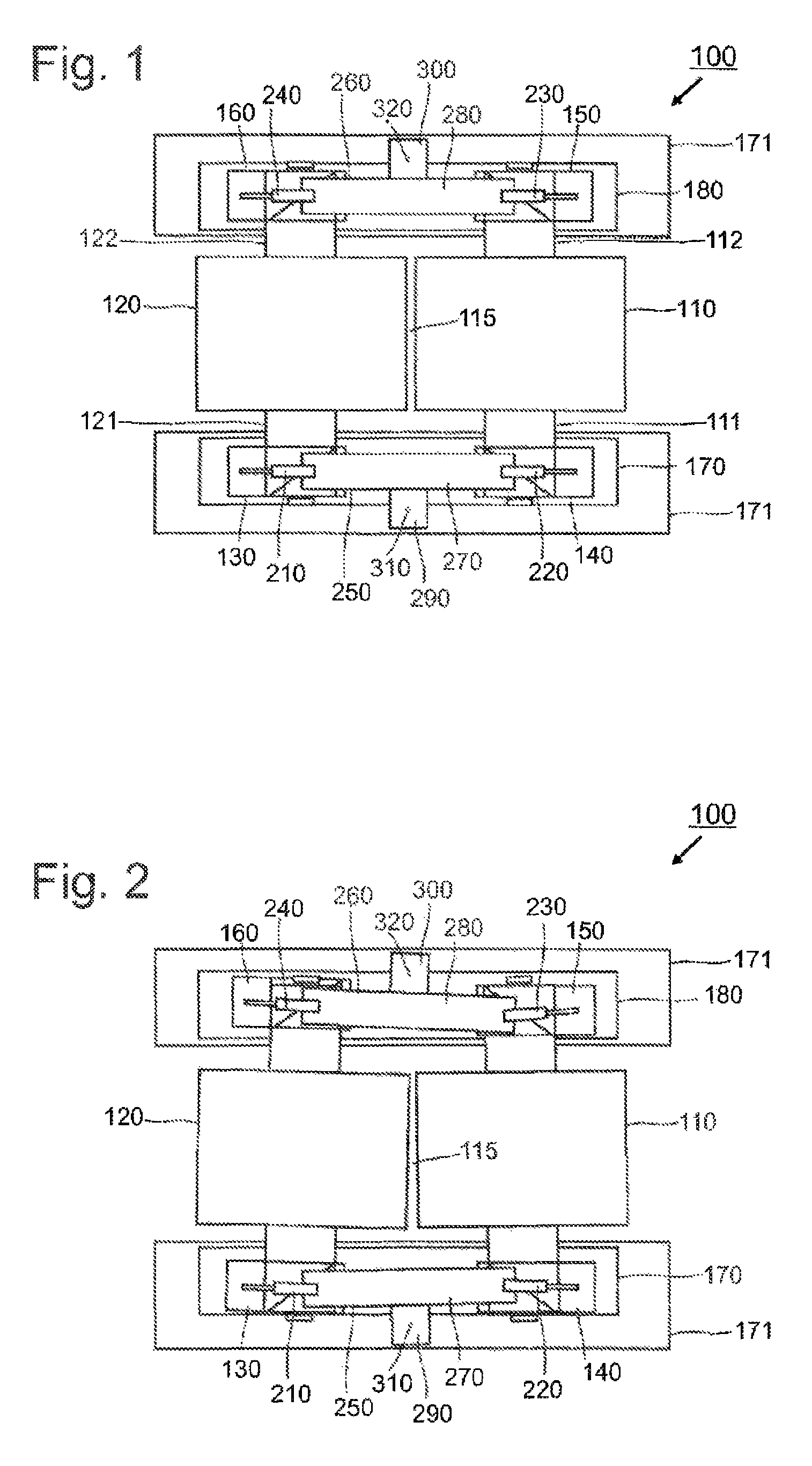
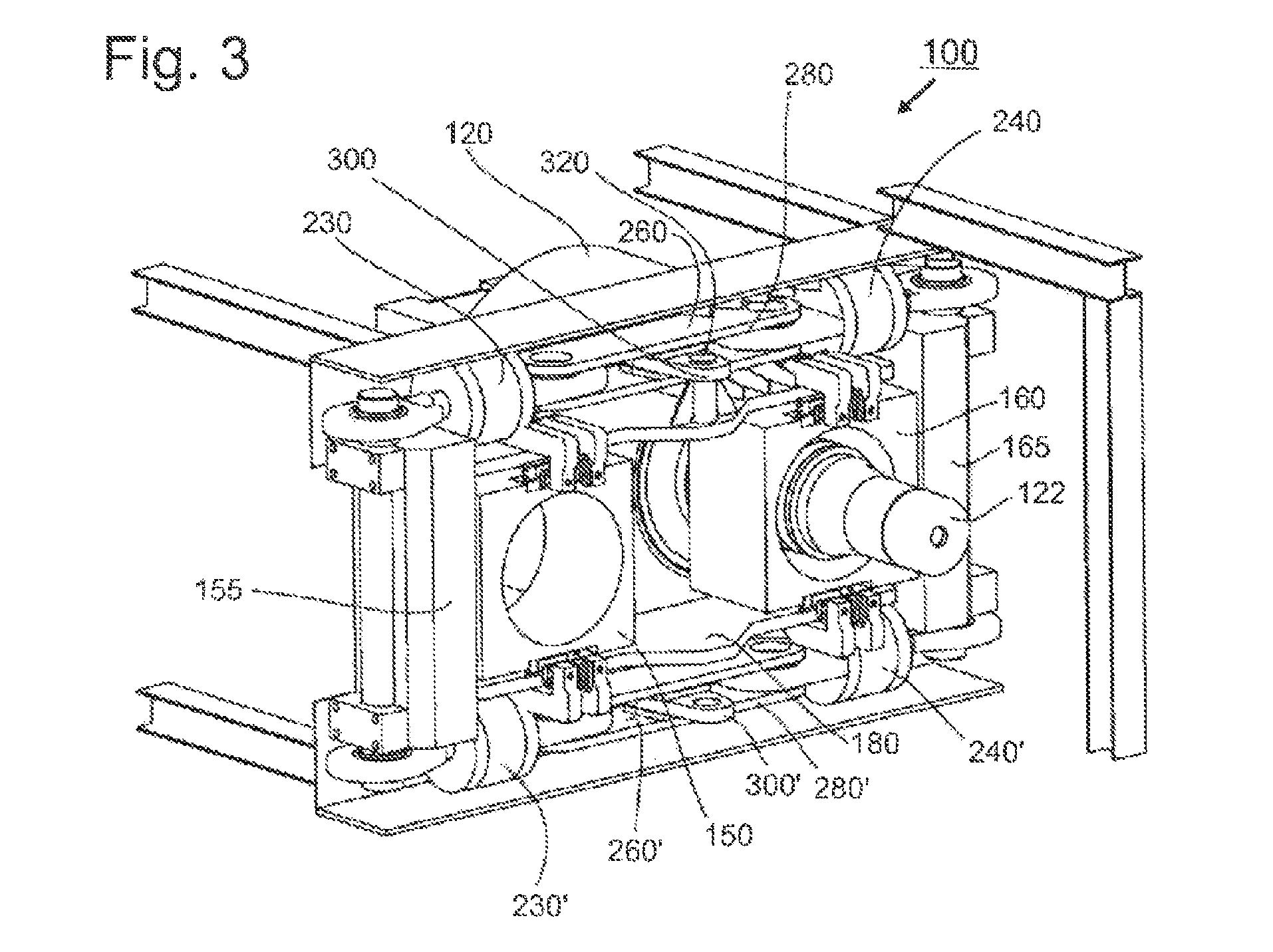
[0008]By a torque balance is understood a rocker-like or pendulum-like suspension mounting, which is acted upon by first and second hydraulic cylinders, which work one against the other in pairs, on opposite-situated arms of the torque balance. These mutually counteracting hydraulic cylinders in each case individually produce the tilting of the torque balance in the direction of the related hydraulic cylinder. This change in position of the torque balance has on the side lying opposite the related first hydraulic cylinder the effect that the opposite-situated second hydraulic cylinder is more strongly loaded and therefore the control circuit of the now more strongly loaded second hydraulic cylinder builds up a higher pressure and acts counter to the first hydraulic cylinder until the torque balance is positioned back in its equilibrium setting. In the inventive roller press, the first and the second hydraulic cylinder have a clutch which is designed to be rotationally movable, so that the first and the second hydraulic cylinder can also act at an angle upon the arms of the torque balance. As a result of this rotationally movable clutch, it is possible that the rolls of the roller press can also assume settings which are not parallel to one another, which is always the case whenever a larger grain outside the middle of the roll gap passes through the roll gap or whenever the roll gap is unevenly charged with grinding stock. The effect of the torque balance is that, via a simple, movably mounted, mechanical element, a roll centering is enforced, insofar as the hydraulic cylinders working to generate the pressure in the roll gap counteract each other. As a result of the torque balance, it is also possible, where necessary, to equalize the force of two non-balanced and mutually counteracting hydraulic cylinders. Hydraulic regulating systems for operating the various cylinders in multi-quadrant operation are not necessary in this case, because the equalization happens automatically.
[0010]The torque balance is mounted in a preferred manner rotatably about a vertical rotation shaft which lies in a plane spanned by the centerline of the roll gap and the vertical. As a result of the vertical rotation axis, the torque balance rotates in a horizontal plane and thus allows a misalignment of the rolls relative to one another, wherein the torque balance has a compensating effect, so that the rolls, in the event of misalignment, are subjected to a force which, following the return of the roller press into the equilibrium setting, causes the rolls of the roller press to stand parallel to one another again.
[0013]In the inventive roller press, the hydraulic cylinders are subjected only to tensile load. The torque balance hence has the effect that the distance apart of the hydraulic cylinders is minimized and the torque balance thereby aligns itself. This produces the centering effect on the roll gap.

Problems solved by technology

In roller presses having rolls with a weight of up to 50 metric tons, an appropriately large dimensioning of the machine frame is necessary, so that, in a necessary and scheduled roll change, the logistics and handling of the machine frame are complex and possible only with appropriately large-sized cranes and disassembly aids.

Method used


Image

  • Roller press having torque balance
  • Roller press having torque balance
  • Roller press having torque balance

Examples


Embodiment Construction

[0019]In FIG. 1, an inventive roller press 100 is depicted in a view from above (parts of a machine frame are blanked out for better representation of the individual parts). In this roller press 100, a first roll 110 is rotatably mounted in the roller press 100 with the aid of shafts -111 and 112. A second, adjacent roll 120, which for its part is rotatably mounted via shafts 121 and 122 in the roller press, is disposed in the roller press 100, with the formation of a roll gap 115 to be centered. During operation of the roller press 100, the two rolls 110 and 120 are driven in counter rotation, so that the grinding stock delivered from above to the roll gap 115 is drawn into the roll gap 115.

[0020]The mounting of the rolls 110 and 120 in the roller press 100 is realized via fixed bearings disposed in the fixed bearing housings 130 and 140 and via loose bearings disposed in the loose bearing housings 150 and 160, which in the roller press 100 lie opposite the fixed bearing housings 1...


PUM


Abstract

A roller press for the pressure treatment or compaction of granular material, having at least two rolls formed as freely rotating rolls, in each case rotatably mounted in a machine frame by a shaft, driven in opposite directions and separated from one another by a roll gap. The shafts of the rolls are accommodated in bearing housings movably mounted in the machine frame and in each case two bearing housings arranged on one side of the rolls and belonging to different rolls are connected to each other via at least one pressure cylinder. The connection between the bearing housings in each case has at least one torque balance. In this way, the structure of a roller press having roller centering is simplified and can be produced more cost-effectively.

Description

BACKGROUND OF THE INVENTION[0001]The invention relates to a roller press for the pressure treatment or compaction of granular material, having at least two rolls, configured as freely rotating rolls, which are respectively rotatably mounted in a machine frame via a shaft, are driven in counter rotation and are separated from one another by a roll gap, wherein the shafts of the rolls are accommodated in bearing housings movably disposed in the machine frame, and wherein in each case two bearing housings disposed on one side of the rolls and belonging to different rolls are connected to each other via at least one pressure cylinder.[0002]For the centering of the roll gap in roller presses for the pressure treatment or compaction of granular material, the rolls of the roller press are generally held by large-sized hydraulic drives in their desired position in order that, on the one hand, the pressure in the roll gap between the rolls is maintained and, on the other hand, as a result of...

Claims


Application Information

Patent Timeline
Patent Type & Authority Patents(United States)
IPC IPC(8): B02C4/32B30B15/04B30B3/04B30B15/00
CPCB30B3/04B02C4/32B30B15/00B30B15/04
Inventor FRANGENBERG, MEINHARD
Owner KHD HUMBOLDT WEDAG GMBH
Learn More