
Electrostatic atomization device

a technology of electrostatic atomization and atomization chamber, which is applied in the direction of electrostatic spraying apparatus, burners, lighting and heating apparatus, etc., can solve the problems of unstable discharge and difficulty in solving the electrostatic atomization device, and achieve the effect of effectively preventing the surplus production of condensed water and preventing the cooling capability from being lowered

Active Publication Date: 2015-08-25
PANASONIC INTELLECTUAL PROPERTY MANAGEMENT CO LTD
View PDF12 Cites 0 Cited by
  • Summary
  • Abstract
  • Description
  • Claims
  • Application Information

AI Technical Summary

Benefits of technology

The present invention provides an electrostatic atomization device that prevents the cooling capability from being lowered due to contact with another member and effectively prevents excess production of condensed water that can destabilize discharging at the distal end of the atomization electrode.

Problems solved by technology

In this manner, it is difficult for the electrostatic atomization device to resolve the problem of the cooling capability being lowered due to contact of the atomization electrode 1 with another member and the problem of discharging being unstable at the distal end of the atomization electrode due to surplus production of the condensed water.

Method used


Image

  • Electrostatic atomization device
  • Electrostatic atomization device
  • Electrostatic atomization device

Examples


Embodiment Construction

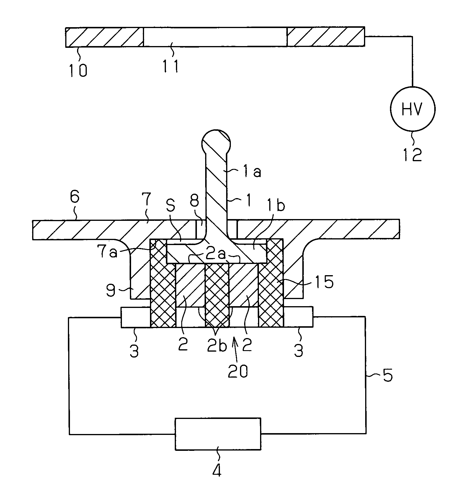
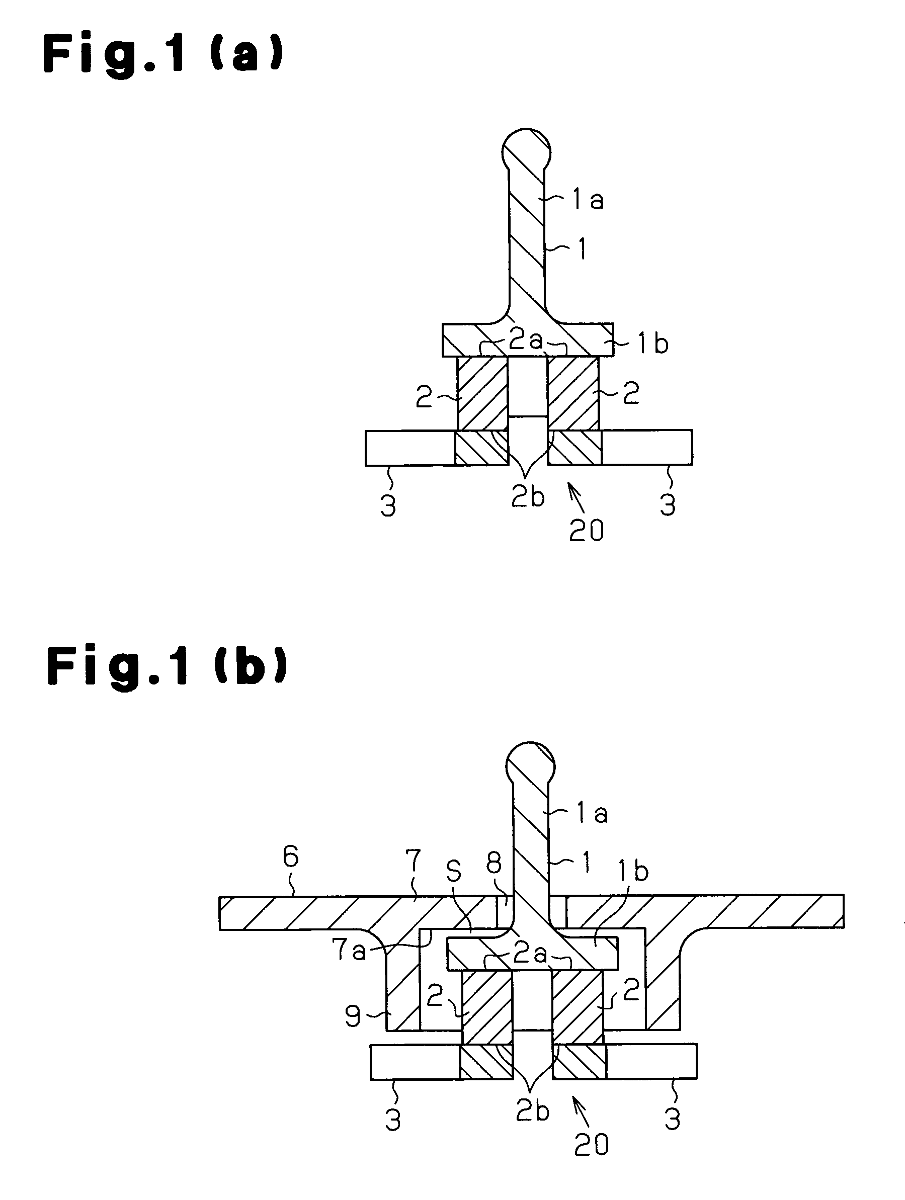
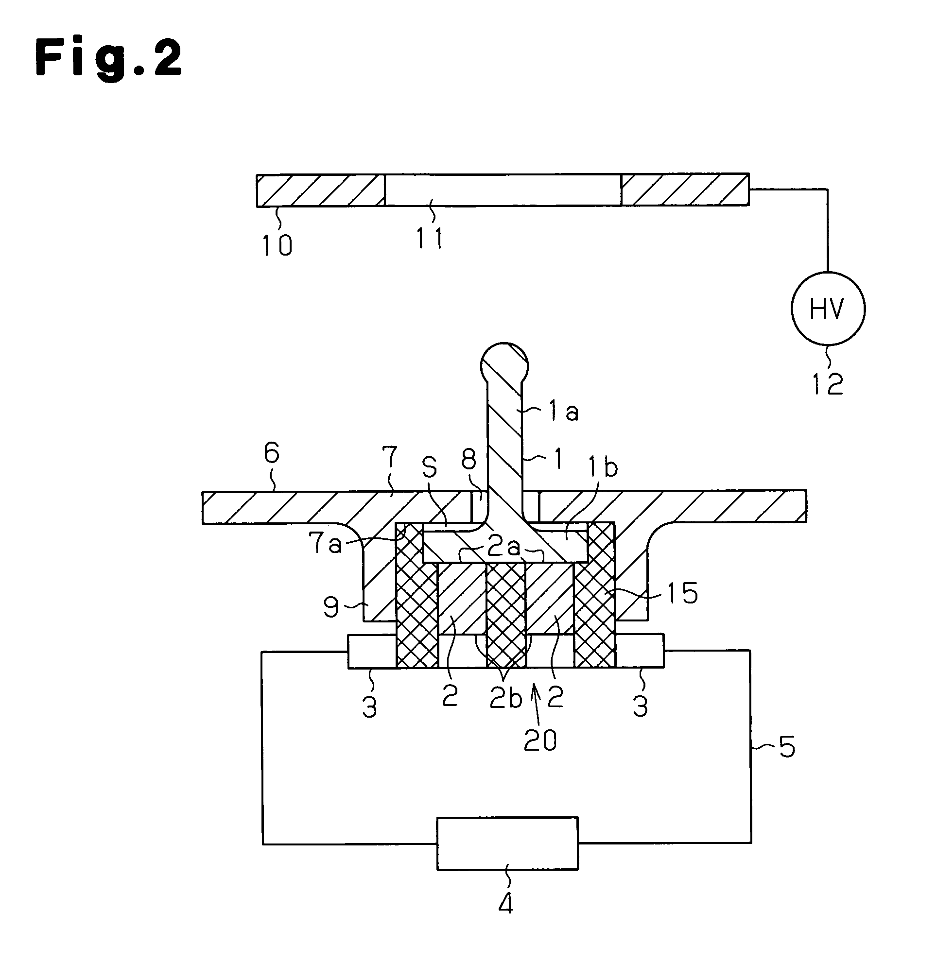
[0014]An electrostatic atomization device according to one embodiment of the present invention will now be discussed with reference to the drawings. FIGS. 1 and 2 show one example of the basic structure of the electrostatic atomization device.

[0015]The electrostatic atomization device includes a cooling unit 20, which serves as a cooling means for cooling an atomization electrode 1. The cooling unit 20 includes a pair of thermoelectric elements 2. The pair of thermoelectric elements 2 includes a P type thermoelectric element and an N type thermoelectric element. Each thermoelectric element has a heat absorption surface 2a and a heat dissipation surface 2b. The heat absorption surface 2a is connected to the atomization electrode 1.

[0016]More specifically, the heat absorption surfaces 2a of the two thermoelectric elements 2 are mechanically and electrically connected to a bottom surface of a base 1b of the atomization electrode 1. The heat dissipation surface 2b of each thermoelectric...


PUM


Abstract

An electrostatic atomization device that prevents the cooling capability from being lowered due to contact of an atomization electrode with another ember, while effectively preventing surplus production of condensed water that would destabilize discharging at the distal end of the atomization electrode. the electrostatic atomization device includes an atomization electrode having a cylindrical electrode body and a base which is informed at a basal end of the electrode body and has a larger diameter than the electrode from the base to produce condensed water on the atomization electrode. Voltage is applied to the atomization electrode when the condensed water is produced to generate charged fine water droplets. A partition plate includes an insertion hole that receives the electrode body of the atomization electrode. The partition plate and the base of the atomization electrode form a water collection region in between.

Description

[0001]This application is a U.S. National Phase of International Application No. PCT / JP2010 / 066117, filed on Sep. 13, 2012, which claims priority to Japanese Patent Application No. 2009-221514, filed on Sep. 25, 2009. The entirety of which is herein incorporated by reference.BACKGROUND OF THE INVENTION[0002]The present invention relates to an electrostatic atomization device that generates charged fine water droplets with condensed water.[0003]Japanese Laid-Open Patent Publication No. 2006-000826 describes an electrostatic atomization device that cools an atomization electrode to produce condensed water. The electrostatic atomization device applies voltage to the atomization electrode to generate charged fine water droplets from the condensed water at the distal end of the atomization electrode.[0004]As shown in FIG. 3, the electrostatic atomization device includes plural pairs of thermoelectric elements 2 held between first and second circuit plates 50, which form a heat conversion...

Claims


Application Information

Patent Timeline
Patent Type & Authority Patents(United States)
IPC IPC(8): B05B5/00F23D11/32B05B5/025B05B5/057
CPCB05B5/0255B05B5/057
Inventor OMORI, TAKAFUMINAKADA, TAKAYUKISUDA, HIROSHIOE, JUNPEIKOBAYASHI, KENTARO
Owner PANASONIC INTELLECTUAL PROPERTY MANAGEMENT CO LTD
Learn More