Lacrosse training and competitive game installation with variable trajectory control

a technology of trajectory control and lacrosse, which is applied in the field of lacrosse ball throwing and training system and competitive game installation with variable trajectory control, can solve the problem that 372 does not disclose the ball projection device which throws balls

Inactive Publication Date: 2015-10-20
SCHWARTZ RALPH
View PDF30 Cites 6 Cited by
  • Summary
  • Abstract
  • Description
  • Claims
  • Application Information

AI Technical Summary

Benefits of technology

[0022]The lacrosse training and competitive game installation is an elongated preferably enclosed space with a player area at one end and a rotatable goal at the distal end. Ball projectors are placed on both sides away from the distal end and closer to the player such that trajectories with significant transverse components are possible. Multiple ball projectors at different heights at each side (such as a low and a high projector) can be used, but the expense and the complexity involved in supplying balls to multiple ball projectors is avoided by using a versatile single ball projector subsystem at each side in this invention.
[0024]In an alternate optional stage two embodiment, the entire ball projector sub-assembly is placed on a motorized lift table (or alternate elevator mechanism) to offer actual height control. This offers more control over the combinations of ball velocity and desired trajectory.

Problems solved by technology

Hayes '372 does not disclose a ball projection device which throws balls at a player at desired angles and trajectories.

Method used


Image

  • Lacrosse training and competitive game installation with variable trajectory control
  • Lacrosse training and competitive game installation with variable trajectory control
  • Lacrosse training and competitive game installation with variable trajectory control

Examples


Embodiment Construction

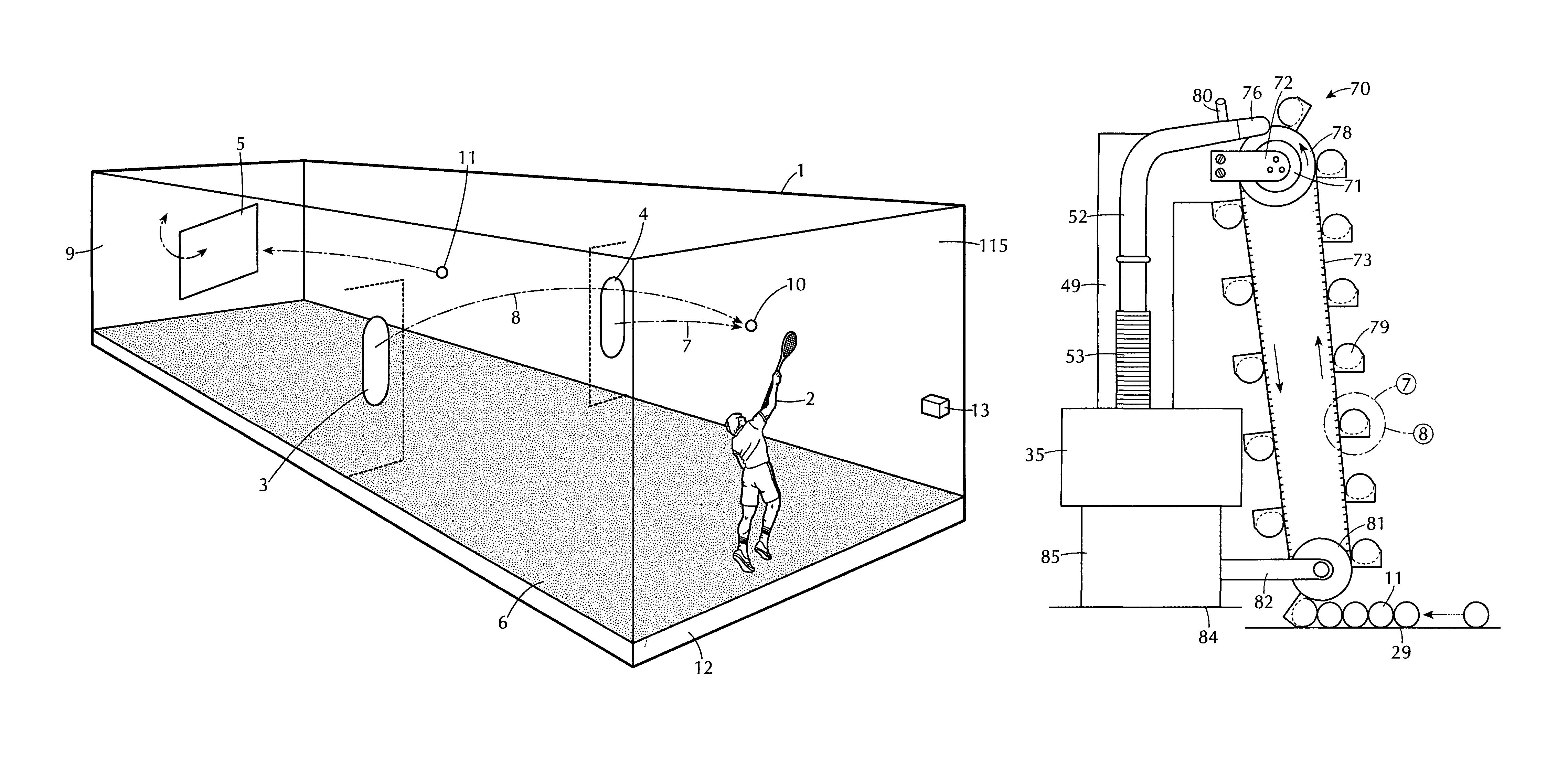
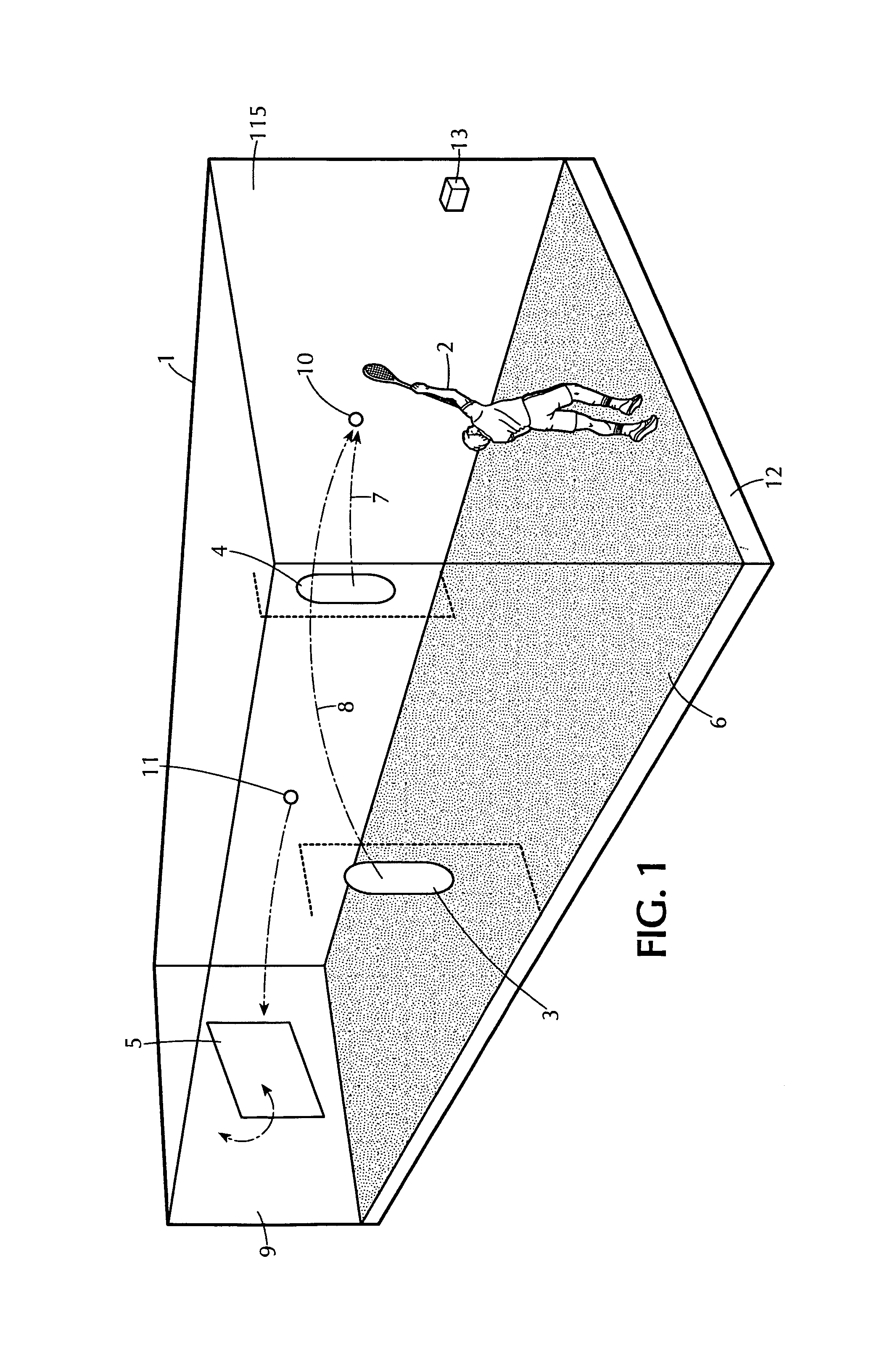
[0041]FIG. 1 shows a lacrosse training and competitive game installation 1 with player region 115, rotatable goal 5 at distal end 9, raised floor 12, player 2, and artificial grass surface 6. While one ball aperture may be used, preferably a pair of oval apertures 3 and 4 are located in side baffles extending forward of the area of goal 5. Oval apertures preferably each house a ball projector on each side and are used to project balls 10 to the player 2. While oval apertures are preferred, it is contemplated that other shaped apertures such as circular or other shaped apertures may be used. Ball 11 is being returned toward the goal 5 which can be rotated a predetermined angle, preferably 45 degrees, from forward in each direction in smaller angle increments, such as 15 degree increments, under computer motor control. Note that ball 10 could have been projected at high speed flat trajectory 7 from the right aperture 4 or as a parabolic high trajectory 8 at low speed from left apertur...


PUM


Abstract

A lacrosse training and competitive game installation includes an elongated enclosed space having side walls and a goal area adjacent one end thereof and a player area at an opposite end thereof. The goal area includes a rear wall and one or more forward projecting side baffle regions projecting forward from the rear wall of the goal area. Each of the one or more side baffle regions has one or more throwing apertures through which lacrosse balls are hurled into the enclosed space in sequence. A ball projector assembly is mounted behind each baffle adjacent each of the throwing apertures for hurling the lacrosse balls into the enclosed space simulating passed balls between players. A simulated goal is preferably rotatable in the goal area for throwing and shooting of balls at various angles to a goal. Balls are collected from the goal area and delivered to each ball projector assembly.

Description

RELATED APPLICATIONS[0001]This application is based upon provisional patent application Ser. No. 61 / 687,406 filed on Apr. 24, 2012, and claims priority therefrom pursuant to 28 U.S. Code §119(e). Applicant incorporates the aforementioned provisional application by reference herein.FIELD OF THE INVENTION[0002]The present invention relates to a lacrosse ball throwing and training system and competitive game installation with variable ball trajectory control.BACKGROUND OF THE INVENTION[0003]U.S. Pat. No. 7,326,132 of Olexa describes a lacrosse shooting range for practicing lacrosse ball throwing with a ball return mechanism.[0004]U.S. Pat. No. 7,166,045 of Linner an ice hockey game platform (a baseball “batting cage” equivalent), a goal with targets, a computer controlled puck circulator, including a magazine of pucks, a passing unit (i.e. “projector”), which passes (i.e. throws) pucks to a player, a conveyor belt which sorts and conveys already shot pucks into the magazine (i.e. reloa...

Claims


Application Information

Patent Timeline
Patent Type & Authority Patents(United States)
IPC IPC(8): A63B69/00A63B71/06A63B47/02A63B69/40A63B71/02A63B63/06A63B63/00A63B24/00
CPCA63B71/0605A63B69/40A63B47/025A63B63/06A63B69/406A63B71/022A63B71/06A63B63/007A63B69/002A63B69/0097A63B2024/0037A63B2063/001A63B2071/0694A63B2220/40A63B2220/833A63B59/20A63B2102/14
Inventor SCHWARTZ, RALPH
Owner SCHWARTZ RALPH
Why Eureka
Try Eureka