Eureka AIR delivers breakthrough ideas for toughest innovation challenges, trusted by R&D personnel around the world.

Firearm handgrip with tool component

a tool and handgrip technology, applied in the field of handgrips, can solve the problems of inability to attach to the interface of the gun, inability to use the gun, and inability to supply a large amount of ammunition, and achieve the effect of convenient attachment interfa

Active Publication Date: 2016-01-05
ANDERSON MARK I +1
View PDF4 Cites 4 Cited by
  • Summary
  • Abstract
  • Description
  • Claims
  • Application Information

AI Technical Summary

Benefits of technology

[0010]To accomplish these objectives, the preferred embodiment of the handgrip is a fore grip comprising a main grip body with a forward slot. The slot contains a lower pivot mount and an upper latch mechanism. A melee component of a type commonly known as “brass knuckles” is insertable in the slot and rests on the pivot mount. The melee component is held in place by the upper latch mechanism. When deployment is desired, the upper latch mechanism is released and the melee component may be pivoted out of the slot, in ready position for use. When not in use, the melee component provides a finger guard for the handgrip and also provides additional gripping capacity. The handgrip of the present invention also provides an easy attachment interface for other useful items and tools, like a bi-pod, knife, or flashlight, by removing the melee component and replacing it with a tool made or fitted with an appropriate interface.

Problems solved by technology

While the firearm can be in and of itself an impressive and effective weapon, there are three inherent limitations to a firearm.
The first is obvious—there is usually a limited supply if ammunition.
The second limitation is that, being a mechanical system, the weapon can fail—in which case the end result is similar to running out of ammunition.
The third limitation is the presence of an ineffective range immediately about the user.
An opponent can, in theory, get too close to the user for effective use of the firearm.
Specialized training in close-quarters combat situations mitigates this limitation by training the user to effectively use the weapon at very short ranges, but the limitation is still present.
These weapons are easily deployed when the primary long firearm is no longer useful and, while they have shorter effective ranges, they also tend to have shorter ineffective ranges.

Method used


Image

  • Firearm handgrip with tool component
  • Firearm handgrip with tool component
  • Firearm handgrip with tool component

Examples


Embodiment Construction

[0030]With reference now to the drawings, the preferred embodiment of the handgrip is herein described. It should be noted that the articles “a”, “an”, and “the”, as used in this specification, include plural referents unless the content clearly dictates otherwise.

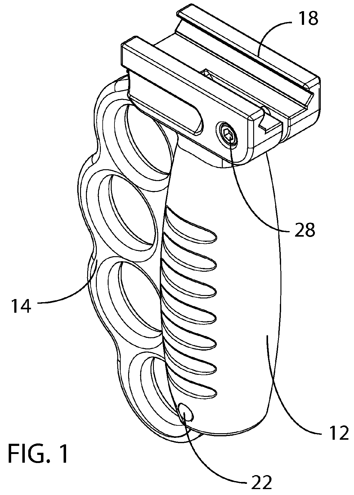
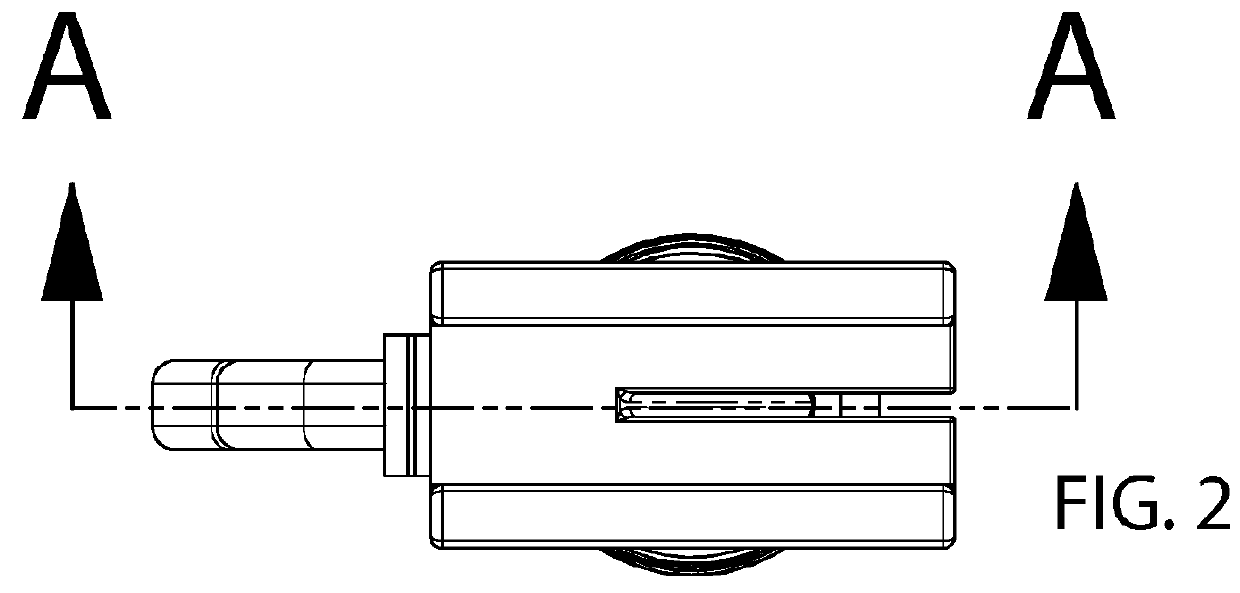
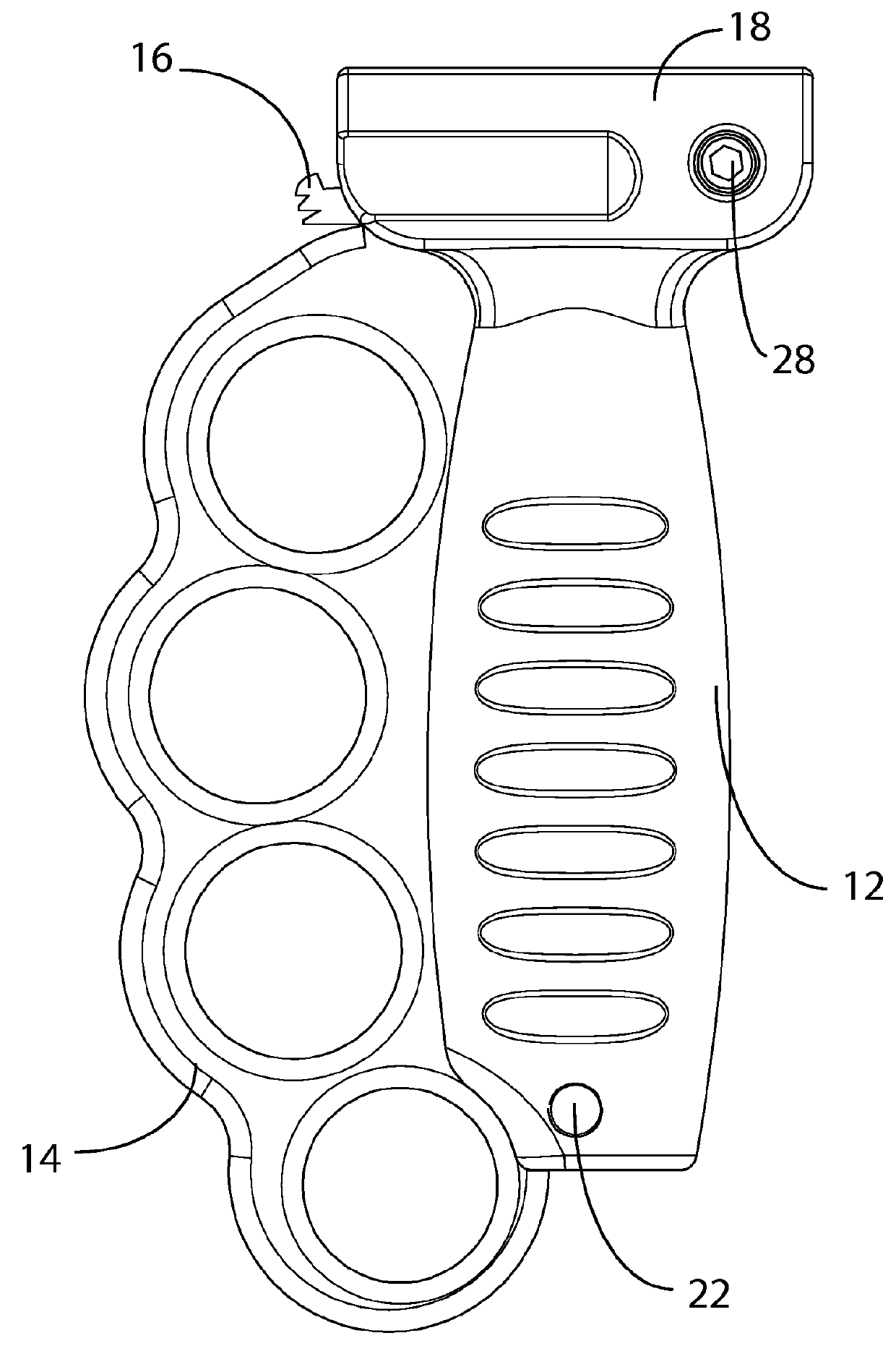
[0031]With reference to FIGS. 1-4, the handgrip comprises a grip body 12 with a tool, such as melee component 14, embedded within. The preferred handgrip is a fore grip, as illustrated, but other grip designs and locations are possible and should be considered as within the purview of the invention. A mounting structure, such as the rail attachment 18, is provided in which to attach the handgrip to a firearm. Any mounting structure known in the art or later developed may be utilized to attach the handgrip to the firearm, such as simple metal straps wrapped around a barrel, as with the first handgrips of about 150 years ago, to the rail system depicted in the drawings here. In the case of the rail attachment of the preferre...


PUM


Abstract

A handgrip for a firearm is disclosed. The handgrip features a tool, in particular a melee component, stowed within a portion of the handgrip, the remaining portion of the melee component forming a finger guard. A latch is provided to hold the melee component in the stowed position. The interface of the melee component with the handgrip component may be either a rotatable interface, utilizing a lower pivot point and a latch such that the melee component may be rotated out of the handgrip or may be a sliding interface, with the melee component sliding within a provided trench. Two latching mechanisms for a rotating interface are disclosed. Other tools, such as bipods and flashlights, may be adapted to also fit the provided trench.

Description

CROSS-REFERENCES TO RELATED APPLICATIONS[0001]This application claims priority on prior filed U.S. Application No. 61 / 900,520, filed Nov. 6, 2013 and incorporates the same by reference in its entirety.FIELD OF THE INVENTION[0002]The present invention relates to the field of firearms and more particularly relates to a handgrip for a long personal firearm which further contains a removable melee component.BACKGROUND OF THE INVENTION[0003]The use of firearms is ubiquitous. Firearms are used in recreational, military and personal security scenarios. One of the most common firearms is a long arm, usually in the form of a personal rifle, shot gun or similar firearm used by an individual and having an extended barrel. These firearms are usually, though not always, held by the user in a manner that braces the butt stock of the firearm against the user's shoulder (dominant hand) while the hand of the opposite shoulder is used to support the barrel. One old invention to aid in the non-dominan...

Claims


Application Information

Patent Timeline
Patent Type & Authority Patents(United States)
IPC IPC(8): F41C23/16F41B15/08F41C23/22
CPCF41C23/16F41B15/08F41C23/22
Inventor ANDERSON, MARK IWARNER, VINCE S.
Owner ANDERSON MARK I
Why Eureka
Eureka Blog
Learn More