Check patentability & draft patents in minutes with Patsnap Eureka AI!

Damper device

a damper device and resonance point technology, applied in mechanical actuated clutches, fluid gearings, gearing, etc., can solve the problems of difficult to exclude the resonance point of the damper device from a wide region, and difficult to suppress the torsional vibration of the engine over a wide region, so as to achieve the effect of suppressing the torsional vibration of the engin

Active Publication Date: 2016-01-12
SUBARU CORP
View PDF6 Cites 3 Cited by
  • Summary
  • Abstract
  • Description
  • Claims
  • Application Information

AI Technical Summary

Benefits of technology

[0009]An aspect of the present invention provides a damper device that is disposed between an engine and a transmission, the damper device having: a torque distribution mechanism comprising a first input element connected to the engine, a second input element connected to the engine via a first elastic member, a first output element connected to the transmission, and a second output element connected to the transmission via a second elastic member; a first clutch disposed between the first output element and the transmission, and switched between an engaged state of connecting the first output element to the transmission and a released state of disconnecting the first output element from the transmission; and a second clutch disposed between the second output element and the transmission, and switched between an engaged state of connecting the second output element to the transmission and a released state of disconnecting the second output element from the transmission.

Problems solved by technology

Through mere adjustment of masses and spring constants in the damper device, however, it is difficult to exclude the resonance point of the damper device from a wide region, extending from a low-revolutions region to a high-revolutions region.
Accordingly, it is difficult to suppress torsional vibration of the engine over a wide region in cases where conventional damper devices are used.

Method used


Image

  • Damper device
  • Damper device
  • Damper device

Examples


Embodiment Construction

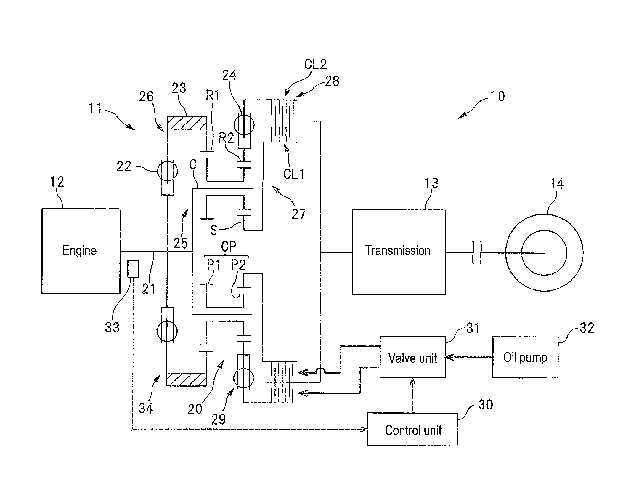
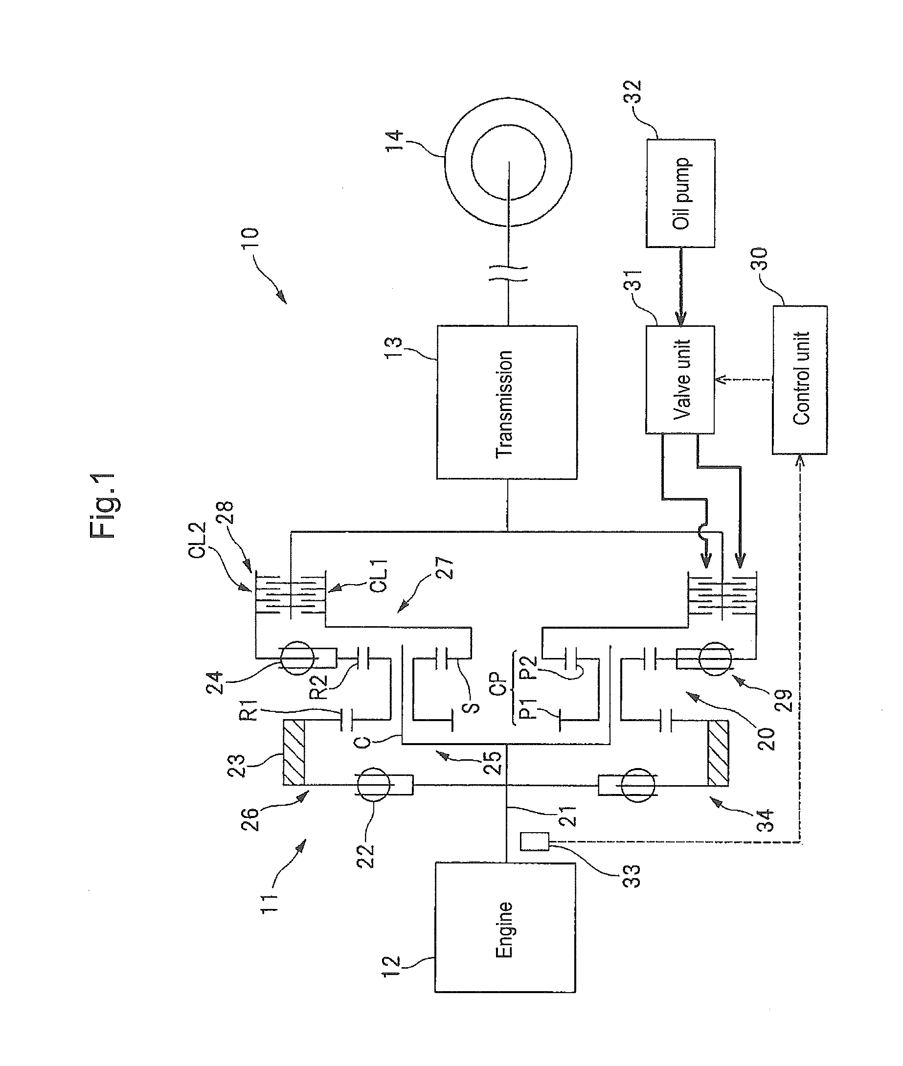
[0026]Implementations of the present invention are explained in detail next with reference to accompanying drawings. FIG. 1 is a schematic diagram illustrating a power unit 10 that is provided with a damper device being a first implementation of the present invention. FIG. 2 is an explanatory diagram illustrating a structure model of the damper device 11 that is built into the power unit 10. FIG. 3A and FIG. 3B are explanatory diagrams illustrating instances of transmission of engine torque. As illustrated in FIG. 1, the power unit 10 has an engine 12, being an internal combustion engine, and a transmission 13 that is connected to the engine 12 via the damper device 11. Thus, the damper device 11 is disposed between the engine 12 and the transmission 13, such that torsional vibration derived from vibration forces of the engine 12 is damped using the damper device 11. As used herein, the term torsional vibration of the engine 12 denotes torque variation derived from, for instance, un...


PUM


Abstract

A damper device is provided between an engine and a transmission and has a torque distribution mechanism that is provided with a first input element connected to the engine, a second input element connected to the engine via a first elastic member, a first output element connected to transmission, and a second output element connected to the transmission via a second elastic member. The damper device further has a first clutch that is provided between the first output element and the transmission and that is switched between an engaged state of connecting the first output element to the transmission and a released state of disconnecting the first output element from the transmission, and a second clutch that is provided between the second output element and the transmission and that is switched between an engaged state of connecting the second output element to the transmission and a released state of disconnecting the second output element from the transmission.

Description

CROSS-REFERENCE TO RELATED APPLICATIONS[0001]The present application claims priority from Japanese Patent Application No. 2013-050701 and 2013-050703, both filed on Mar. 13, 2013, the entire contents of which are hereby incorporated by reference.BACKGROUND[0002]1. Technical Field[0003]The present invention relates to a damper device that is disposed between an engine and a transmission.[0004]2. Related Art[0005]A damper device is disposed between an engine and a transmission in order to reduce torsional vibration that is transmitted from the engine to the transmission. For example, a damper has been proposed that comprises two flywheels connected to each other via a spring (see PCT International Publication No. WO 2012 / 66680 A1).[0006]The connection of the two flywheels via the spring can suppress the torsional vibration of the engine.[0007]Damper devices are designed so as to exclude a resonance point (natural frequency) of the damper device from a normal region of engine revolutio...

Claims


Application Information

Patent Timeline
Patent Type & Authority Patents(United States)
IPC IPC(8): F16F15/14F16D13/38F16H47/08B60K17/346F16H1/28
CPCF16F15/1478F16D13/385B60K17/3467F16H1/28F16H47/08Y10T477/753F16D48/062F16D2500/3067F16D2500/50293F16D2500/525F16F15/1206
Inventor UKON, YASUYUKIMURAKAMI, MAMORUSUZUKI, YUUKISHINOHARA, TSUYOSHI
Owner SUBARU CORP
Features
  • R&D
  • Intellectual Property
  • Life Sciences
  • Materials
  • Tech Scout
  • Unparalleled Data Quality
  • Higher Quality Content
  • 60% Fewer Hallucinations
Learn More