Engine starting device and engine starting method
a technology of engine starting and engine rotation, which is applied in the direction of engine starting, machines/engines, instruments, etc., can solve the problems of taking time for the engine rotation to be completely stopped and carrying out the restart, and achieve the effect of quick and quiet restarting the engin
- Summary
- Abstract
- Description
- Claims
- Application Information
AI Technical Summary
Benefits of technology
Problems solved by technology
Method used
Image

Examples
first embodiment
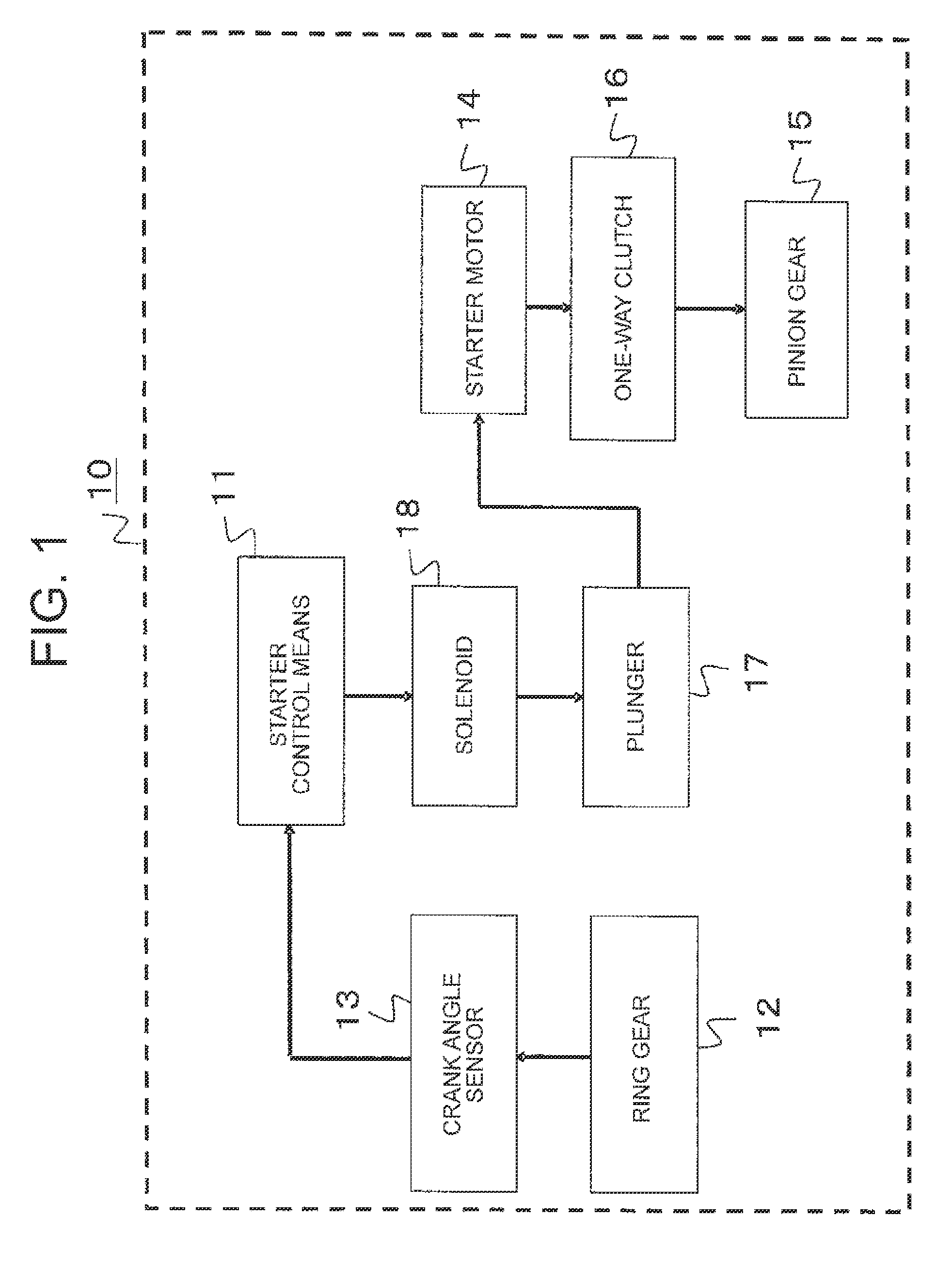
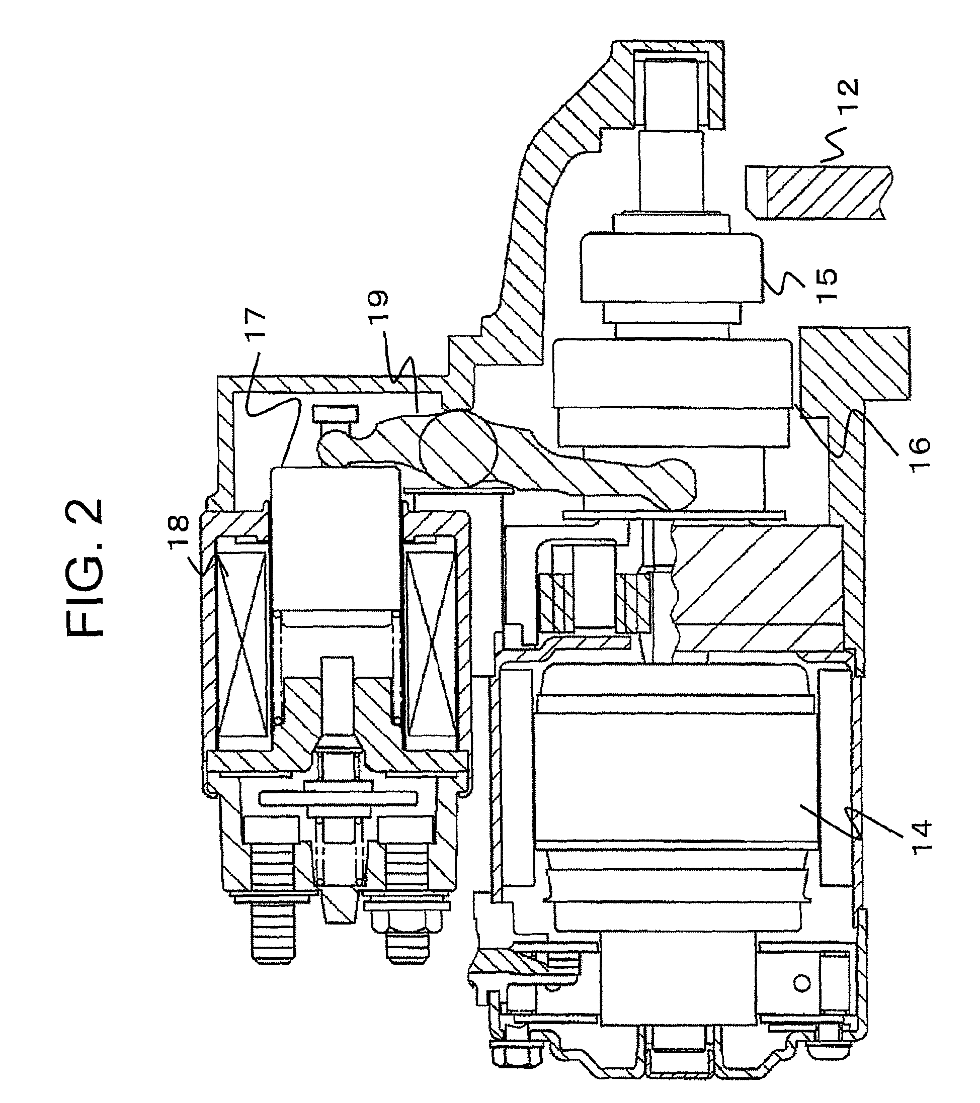
[0034]FIG. 1 is a block diagram illustrating a schematic configuration of an engine starting device 10 according to a first embodiment of the present invention. Moreover, FIG. 2 is a cross-sectional view of a starter of the engine starting device according to the first embodiment of the present invention.
[0035]The engine starting device 10 according to this embodiment illustrated in FIG. 1 includes starter control means 11, a ring gear 12, a crank angle sensor 13, a starter motor 14, a pinion gear 15, a one-way clutch 16, a plunger 17, and a solenoid 18.
[0036]The starter control means 11 controls power supply to the solenoid 18. The power supply to the solenoid 18 results in the attraction of the plunger 17, thereby moving the pinion gear 15 via a lever 19 (refer to FIG. 2) and as a result, the pinion gear 15 and the ring gear 12 mesh with each other. Moreover, the movement of the plunger 17 closes a contact, and the electric power is thus supplied to the starter motor 14, and as a ...
second embodiment
[0073]In the above-mentioned first embodiment, the first predetermined rpm N1 and the second predetermined rpm N2 are set as constant rpms. However, these predetermined rpms are not necessarily constant values, and the values may be set for each crank angle depending on engine pulsation, for example.
[0074]Thus, according to a second embodiment, referring to FIGS. 7 to 10, a description is given of a case where the first predetermined rpm N1 and the second predetermined rpm N2 are defined depending on the crank angle of the engine.
[0075]FIG. 7 is a conceptual view showing a case where the first predetermined rpm N1 is a constant value according to the second embodiment of the present invention. On the other hand, FIG. 8 is a conceptual view showing a case where the first predetermined rpm is changed depending on the crank angle of the engine according to the second embodiment of the present invention.
[0076]During the inertial rotation of the engine, before and after the compression t...
third embodiment
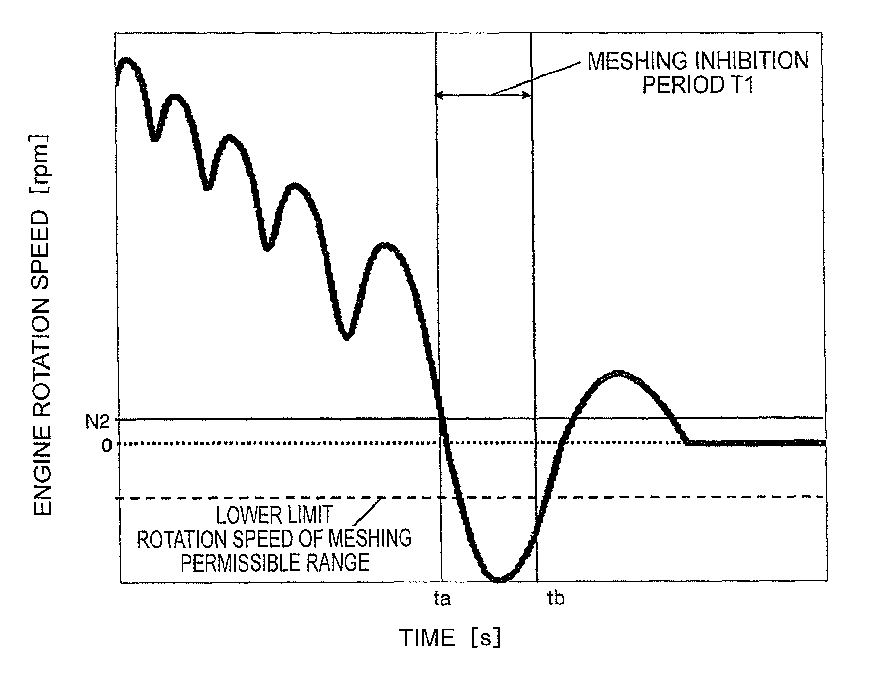
[0093]In the above-mentioned first and second embodiments, a description has been given of the case where the release of the meshing inhibition condition is determined based on whether or not the elapsed time T after the meshing inhibition condition is established is longer than the predetermined time T1. In contrast, according to a third embodiment, a description is given of a case where whether or not to release the meshing inhibition condition is determined based on the engine rpm.
[0094]FIG. 12 is a conceptual view showing a backward rotation peak of the engine according to the third embodiment of the present invention. If the engine presents the inertial rotation due to the idle-stop and the engine rotates backward while the meshing inhibition condition is established, a peak (time tk in FIG. 12) of the backward rotation can be determined by determining a change rate in engine rpm for each calculation period or each angle. Thus, according to the third embodiment, the meshing inh...
PUM
 Abstract
Description
Claims
Application Information
 - Generate Ideas
- Intellectual Property
- Life Sciences
- Materials
- Tech Scout
- Unparalleled Data Quality
- Higher Quality Content
- 60% Fewer Hallucinations
Browse by: Latest US Patents, China's latest patents, Technical Efficacy Thesaurus, Application Domain, Technology Topic, Popular Technical Reports.
© 2025 PatSnap. All rights reserved.Legal|Privacy policy|Modern Slavery Act Transparency Statement|Sitemap|About US| Contact US: help@patsnap.com