Female connector and card edge connector

a card edge connector and female connector technology, applied in the direction of connection, electrical apparatus, coupling device connection, etc., can solve the problem of difficult cooling efficiency, and achieve the effect of efficient utilization of card member space with the substrate, smooth efficient connection, and efficient utilization of card member spa

Inactive Publication Date: 2016-03-08
JST MFG CO LTD
View PDF9 Cites 3 Cited by
  • Summary
  • Abstract
  • Description
  • Claims
  • Application Information

AI Technical Summary

Benefits of technology

[0044]The female connector of the first and second aspects is disposed with multiple stages, for example, three stages, of contacts on one side relative to the inner space in which the card member is located and a stage of contacts on the other side to make the arrangement of the contacts asymmetric. By making the configuration of the female connector asymmetric, for example, multiple circuit wirings for signals can be formed on a mounting surface on one side of the substrate while only the circuit wiring for a power source can be disposed on the other side of the substrate. As a result, since the other side of the substrate can be formed thinner, a heat sink etc., for cooling can be disposed on the side with the circuit wiring for a power source. Therefore, the female connector of the first aspect enables usage of the card member with the space of the substrate efficiently utilized.
[0045]When the multiple circuit wirings for signals are formed on the mounting surface on one side of the substrate and only the circuit wiring for a power source is disposed on the other side of the substrate in the female connector of the third aspect, the circuit wirings for signals can be connected to multiple stages of the first contacts and the relay terminals coupled to the second contacts disposed on one side of the female connector and the circuit wiring for a power source can be connected to a stage of the first contacts disposed on the other side of the female connector. Therefore, the female connector of the second aspect enables smooth efficient connection to the card member with the space of the substrate efficiently utilized.
[0046]According to the female connector of the fourth aspect, since the relay terminals can be fixed at the correct positions of the housing and the relay terminals can be restrained from moving due to an external force, the relay terminals can correctly be connected to the card edge terminals at predetermined positions.
[0047]According to the female connector of the fifth aspect, since the rib formed in the inner space of the housing integrates the inner space of the housing, the inner space can be restrained form expanding outward, and deformation of the housing and deterioration in contact pressure due to the deformation can be suppressed. A wide female connector can be supported by disposing a plurality of the ribs. These ribs act as portions to which slits disposed in the substrate of the card members are fitted.
[0048]According to the female connector of the sixth aspect, since the relay terminals are covered by the lid body, application of an external force is suppressed and the relay terminals can be prevented from coming off. The pressing portion of the lid body can press the relay terminals for prevention of coming off etc., and can restrain reduction in contact pressure.
[0049]According to the female connector of the seventh aspect, since the housing is divided, the housing having a complicated shape can easily be formed.

Problems solved by technology

Since the power circuits generate heat due to energization, the absence of efficient cooling may cause a trouble in another signal circuit or electric components mounted on the substrate.
Since the substrate is located at the center of the housing, efficient cooling may become difficult because of obstacles such as cooling members disposed on the power circuit sides of one and the other sides.

Method used


Image

  • Female connector and card edge connector
  • Female connector and card edge connector
  • Female connector and card edge connector

Examples


Embodiment Construction

[0072]Preferred embodiments of the present invention will now be described with reference to the drawings. The following embodiments are mere exemplifications of a female connector and a card edge connector for embodying a technical concept of the present invention and are not intended to limit the present invention thereto. The present invention is equally applicable to other embodiments included in claims.

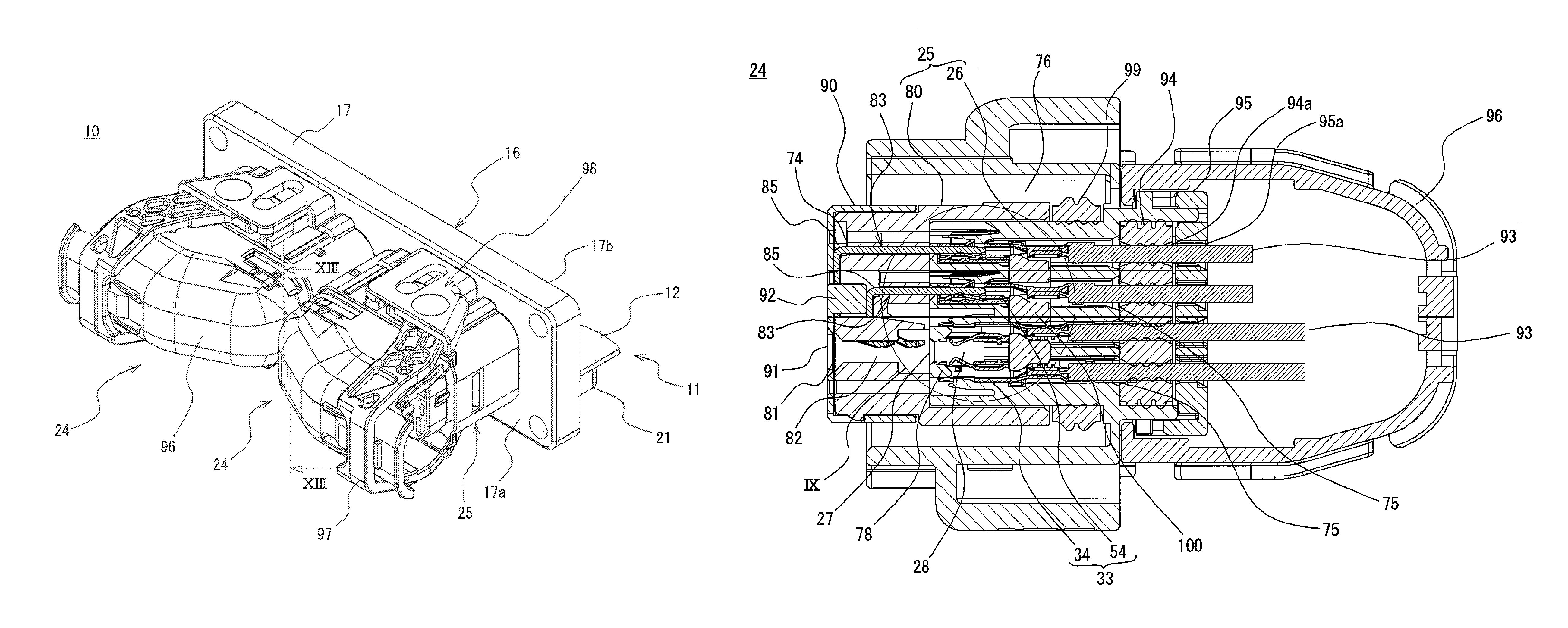
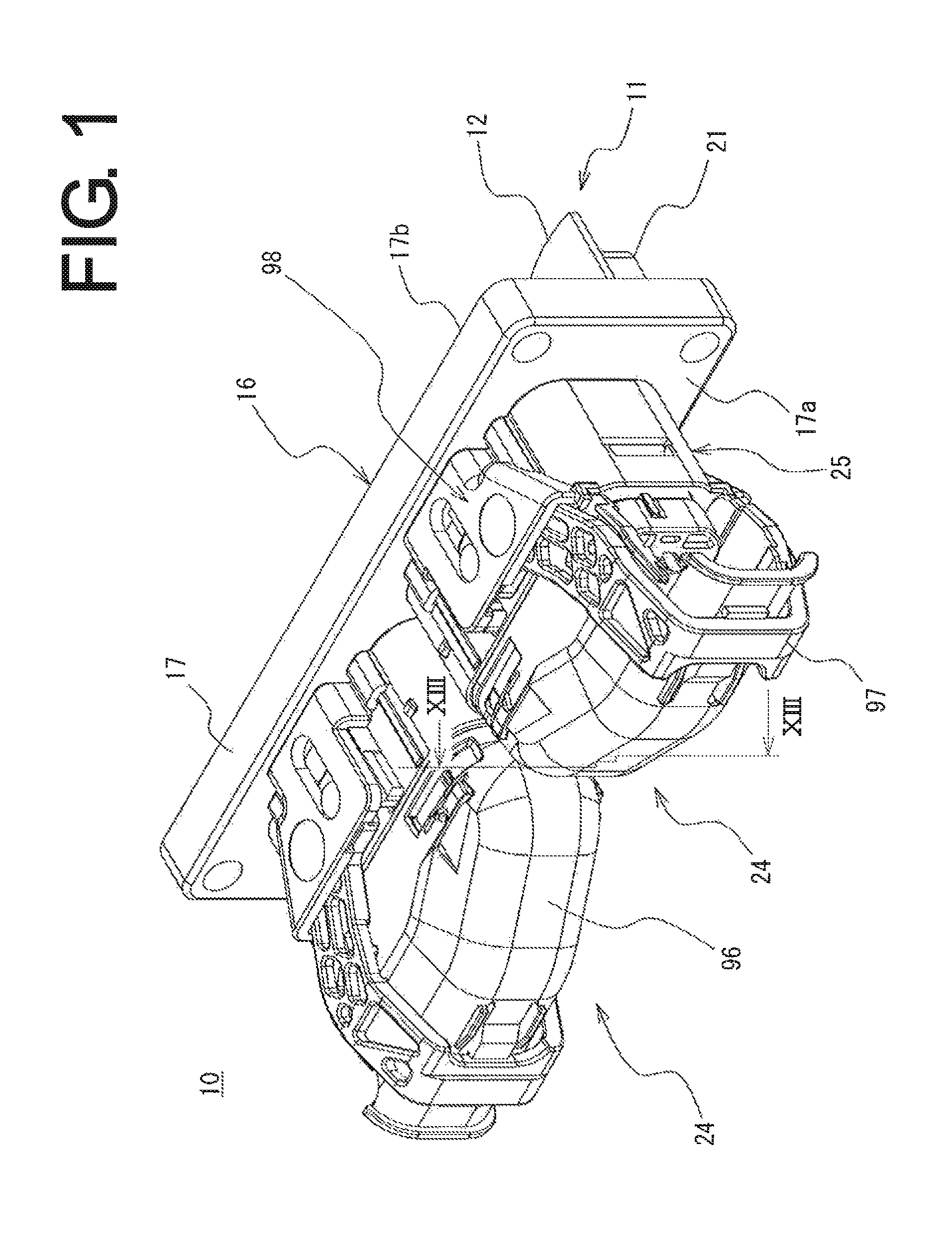
[0073]A card edge connector 10 according to an embodiment will be described with reference to FIGS. 1 to 13. The card edge connector 10 of the embodiment is made up of a card member 11 and a female connector 24 to which the card member 11 is connected, as depicted in FIG. 1. A card housing 16 is attached to the card member 11 of FIG. 1.

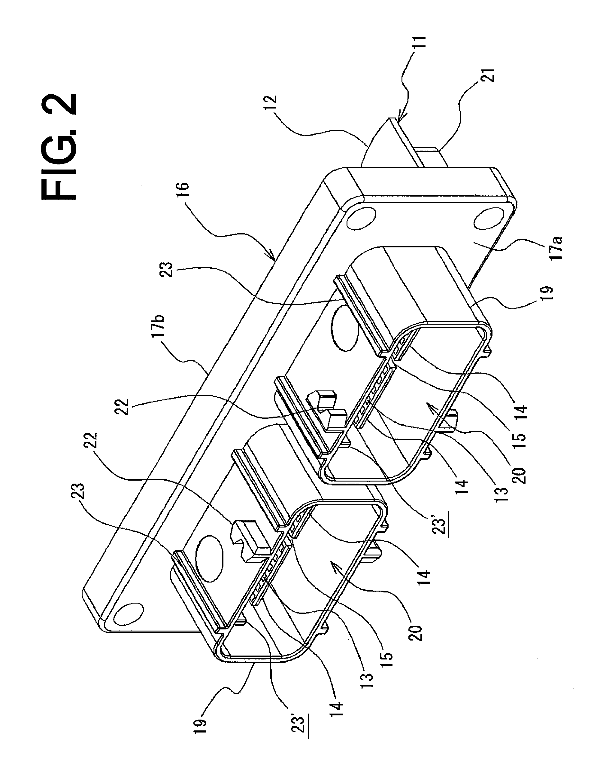
[0074]The card member 11 of the embodiment will be described with reference to FIGS. 1 to 5. The card member 11 is made up of a substrate 12 disposed with circuit wiring etc., (not depicted) and having a card edge portion 14 having in one and the o...


PUM


Abstract

A female connector has a plurality of contacts to be connected to a card member having a card edge portion with a plurality of card edge terminals formed on a substrate, and a housing disposed with contact housing portions, and the housing has a flat opening portion on one side into which the card edge portion is inserted, an insertion port on the other side, and an inner space therein communicating with the flat opening portion and disposed with the card edge portion, and the contact housing portion has at least two stages of first contact housing portions formed on one side relative to the inner space of the housing and communicating with the insertion port, and a stage of second contact housing portions formed on the other side relative to the inner space of the housing and communicating with the insertion port.

Description

BACKGROUND OF THE INVENTION[0001]The present invention relates to a female connector and a card edge connector connected to a card member having card edge terminals formed on an end portion of a substrate and particularly to a female connector and a card edge connector connected to a card member having different numbers of contacting terminals between a mounting surface side of a substrate and an opposite side thereof.[0002]A so-called card edge substrate is known that has card edge terminals formed on an end portion of the substrate for directly connecting the substrate and a connector when the substrate with printed electronic circuits etc., is connected to an electronic device etc., and a so-called card edge connector is also known that is formed by combining this card edge substrate etc., with a counterpart female connector.[0003]With regard to card edge connectors, for example, as disclosed in Japanese Laid-Open Patent Publication No. 2009-176625, a card edge connector is known...

Claims


Application Information

Patent Timeline
Patent Type & Authority Patents(United States)
IPC IPC(8): H01R4/50H01R13/625H01R12/75H01R12/72
CPCH01R12/75H01R12/721
Inventor NAGAMINE, AKIRA
Owner JST MFG CO LTD
Why Eureka
Try Eureka