Washing machine suspension ball support

a technology of ball support and washing machine, which is applied in the direction of other washing machines, springs/dampers, textiles and paper, etc., can solve the problems of unintended disengagement, field failure, and sudden shift of load, and achieve the effect of inhibiting unintended disengagement of parts

Inactive Publication Date: 2016-03-29
ILLINOIS TOOL WORKS INC
View PDF27 Cites 3 Cited by
  • Summary
  • Abstract
  • Description
  • Claims
  • Application Information

AI Technical Summary

Benefits of technology

[0008]In one aspect of a form of the washing machine ball suspension the ball suspension support is engaged with the rod in a first position and inverted to fully engage the parts, thereby inhibiting unintended disengagement of the parts during manipulation or handling of the appliance.
[0009]In another aspect of a form of the washing machine ball suspension the ball suspension support can be used with known suspension arms to more positively engage the parts.

Problems solved by technology

Without control or damping, the load can shift abruptly, due to the agitating and spinning actions of a wash cycle.
However, handling of the washing machine during shipping, installation or servicing can alter the designed upright orientation of the machine, allowing the rod to slide out of the ball suspension support and become disengaged therefrom, thereby causing a field failure.
Other than the hook end of the rod engaging the end of the ball support, the rod is not otherwise secured to the ball support, and nothing in the structure of the rod or the ball support prevents or inhibits the rod and ball support from axial movement relative to one another sufficient to disengage the parts from each other.
For example, inverting the washer can cause unintended disengagement.

Method used


Image

  • Washing machine suspension ball support
  • Washing machine suspension ball support
  • Washing machine suspension ball support

Examples


Embodiment Construction

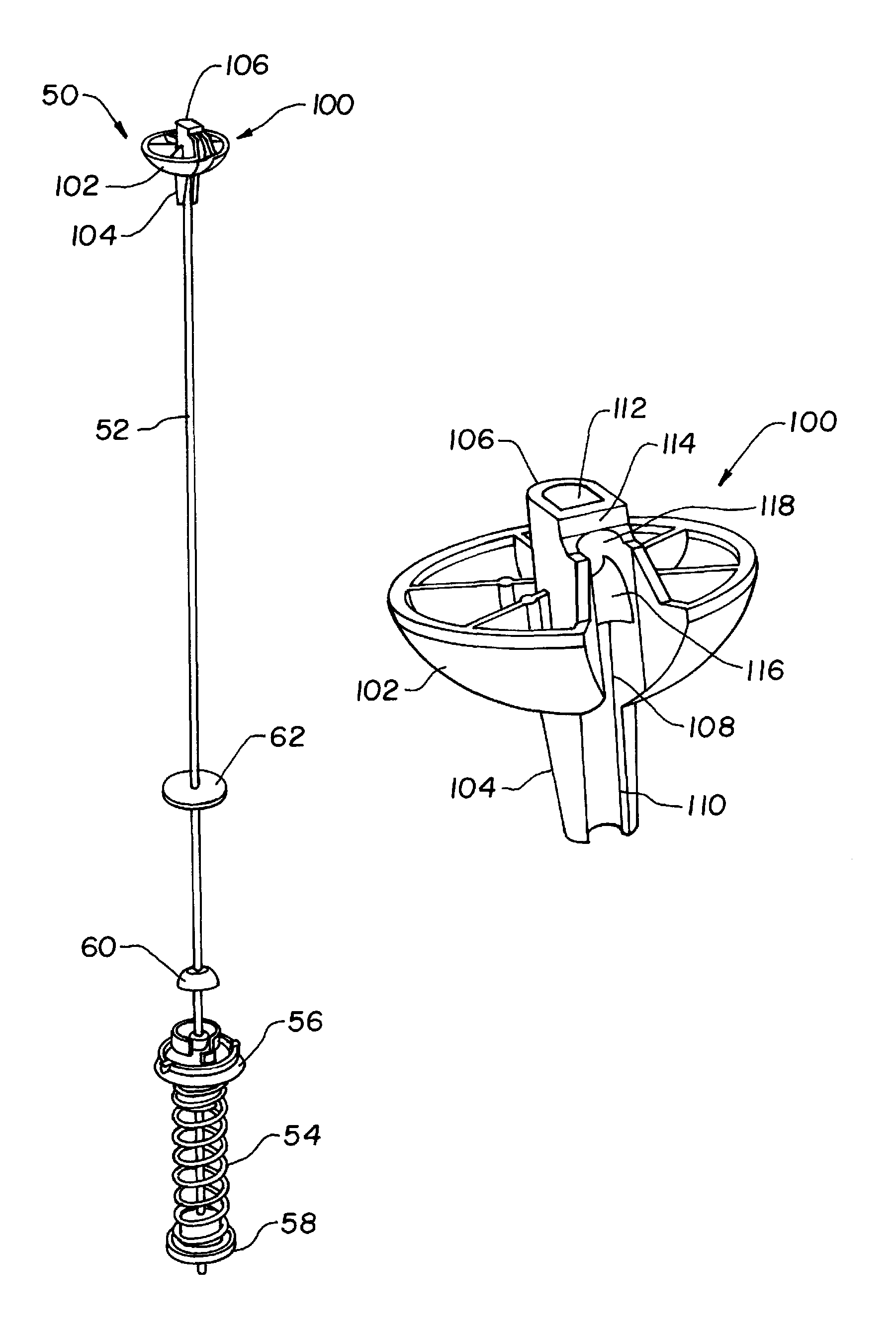
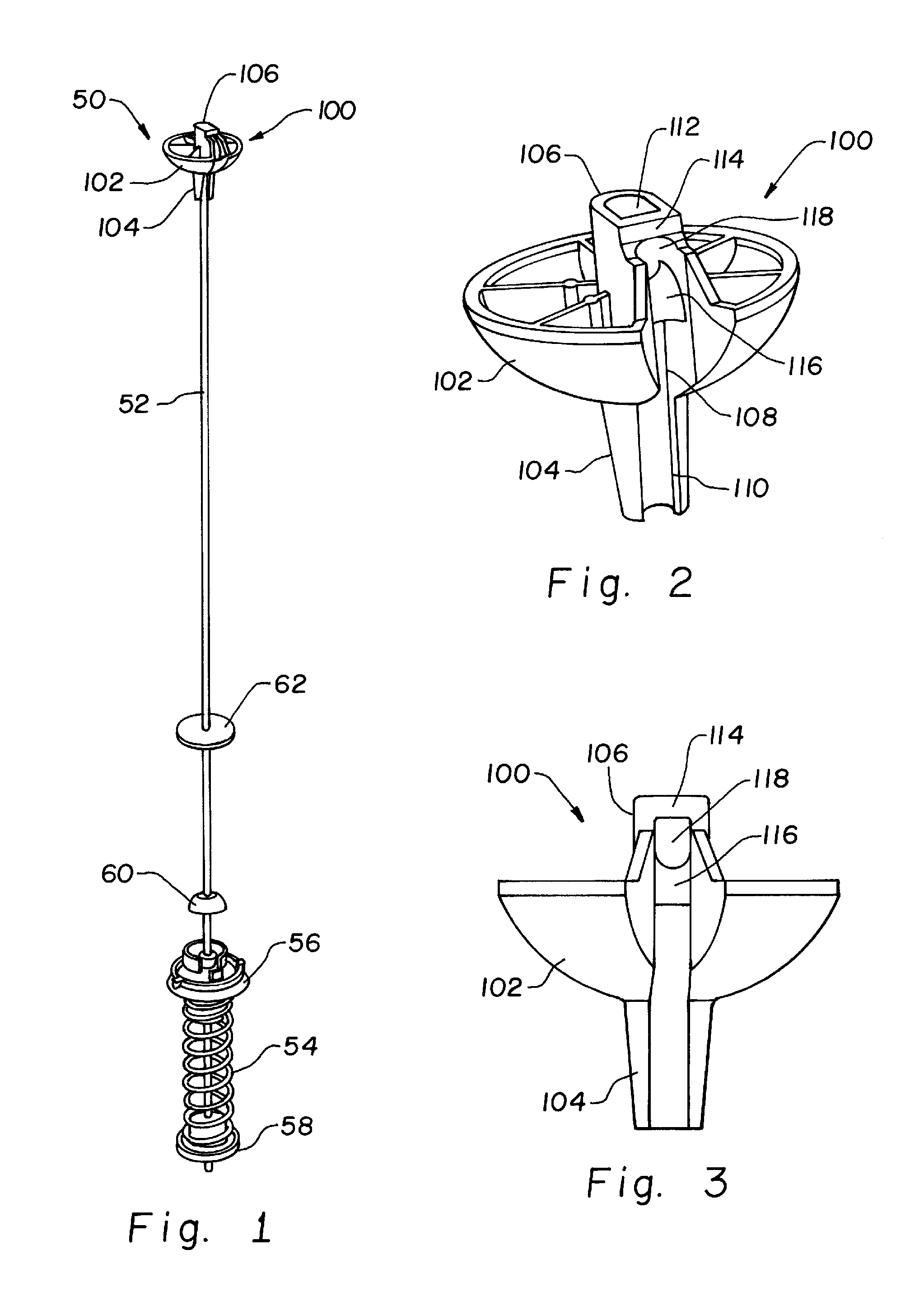
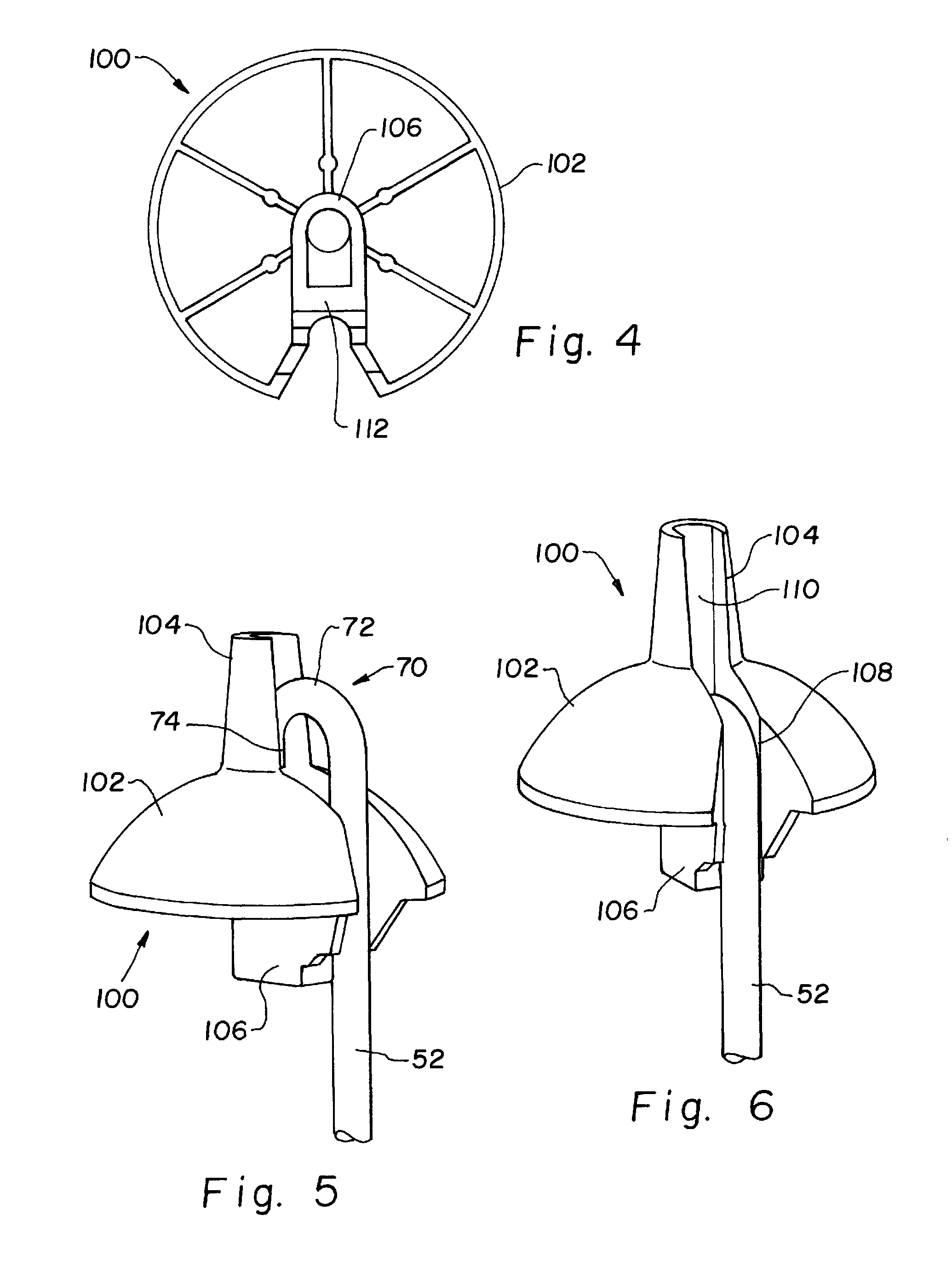
[0020]Referring now more particularly to the drawings and to FIG. 1 in particular, there is shown a washing machine tub suspension arm assembly 50 including a suspension rod 52. Suspension arm assembly 50 is configured at a lower end for attachment to a tub of a top loading washing machine, and includes a spring 54 and various spring retainers 56, 58 and spacers or washers 60, 62 disposed on the lower end of suspension rod 52. At the opposite end, which is the upper end when fully installed, suspension rod 52 forms a hook 70 having a curved portion 72 and a return segment 74 leading to an end 76. A ball support 100 as disclosed herein is provided at hook 70 for suspending suspension arm assembly 50 from a frame member of the washing machine. It should be understood that ball support 100 disclosed herein can be used on standard rods 52 using known features for attachment to the tub of a washing machine. Accordingly, rod 52 including hook 70, spring 54 spring retainers 56, 58, spacers...


PUM


Abstract

A ball support for a suspension rod in top loading washing machines includes a main body, a support segment and a hook capture head for securing the hooked end of the rod between spaced bars of the cylindrical rod support. Attaching and detaching the ball support from the rod requires inversion of the parts relative to one another.

Description

CROSS-REFERENCE TO RELATED APPLICATIONS[0001]The present application is a National Phase of PCT / US2013 / 022849 filed Jan. 24, 2013 claims the benefits of U.S. Provisional Application Ser. No. 61 / 590,576, filed Jan. 25, 2012.FIELD OF THE INVENTION[0002]The present invention relates generally to washing machines, and, more particularly, to the suspension systems supporting and controlling movement of the washer drum or tub in a top loading washing machine.BACKGROUND OF THE INVENTION[0003]A top loading washing machine includes a suspension system to hold the washer drum or tub within the appliance frame, and to control movement of the washer drum or tub. In simple form, the suspension system connects the tub to the frame via springs that control and moderate the movement of the tub as the washing machine operates through various cycles and the load of water and garments or other items in the tub shifts. Without control or damping, the load can shift abruptly, due to the agitating and sp...

Claims


Application Information

Patent Timeline
Patent Type & Authority Patents(United States)
IPC IPC(8): D06F37/24D06F37/22D06F37/20D06F37/26F16F15/067
CPCD06F37/24D06F37/20D06F37/22D06F37/262D06F37/263D06F37/264D06F37/265F16F15/067
Inventor WONG, CHONG, B.DAVIS, MICHAEL, W.
Owner ILLINOIS TOOL WORKS INC
Why Eureka
Try Eureka