Grease coupler

a coupler and grease technology, applied in the direction of couplings, pliable tubular containers, manual lubrication, etc., can solve the problems of short service life, difficult disconnection of the coupler from the nipple, and distinct negative effect when it comes to disconnection under pressur

Active Publication Date: 2015-02-17
GURTECH
View PDF10 Cites 23 Cited by
  • Summary
  • Abstract
  • Description
  • Claims
  • Application Information

AI Technical Summary

Benefits of technology

[0010]Movement of the sleeve member is effected by means of a trigger pivotally mounted on the elongate body and attached via a linkage mechanism associated with the rear end of the sleeve member. The trigger is squeezed by an operator to draw the sleeve member backwards along the body against the bias of the spring, allowing the clamping elements to become uncompressed and in so doing permit receipt of the nipple. Release of the trigger causes the inherent bias of the spring to slide the sleeve member forward over the clamping elements to positively engage the grease nipple.
[0014]The manually operated trigger mechanism allows for the tapered sleeve to be retracted against a spring load by a mechanical linkage. The trigger mechanism and linkage is designed such that the leverage works in the favor of the operator to allow for ease of activation even under a highly pressurized scenario.

Problems solved by technology

The negative to this scenario is that when there remains a positive pressure within the delivery line at the end of the greasing cycle it becomes very difficult to disengage the coupler from the nipple.
The majority of the modern versions make use of a permanent internal seal which is a positive for reducing bypass during greasing, however has a distinct negative effect when it comes to disconnecting under pressure.
In the course of such action the coupler and the nipple often become damaged and result in relatively short service life.

Method used


Image

  • Grease coupler
  • Grease coupler
  • Grease coupler

Examples


Embodiment Construction

[0022]Referring to the drawings the apparatus for an improved grease coupler is detailed.

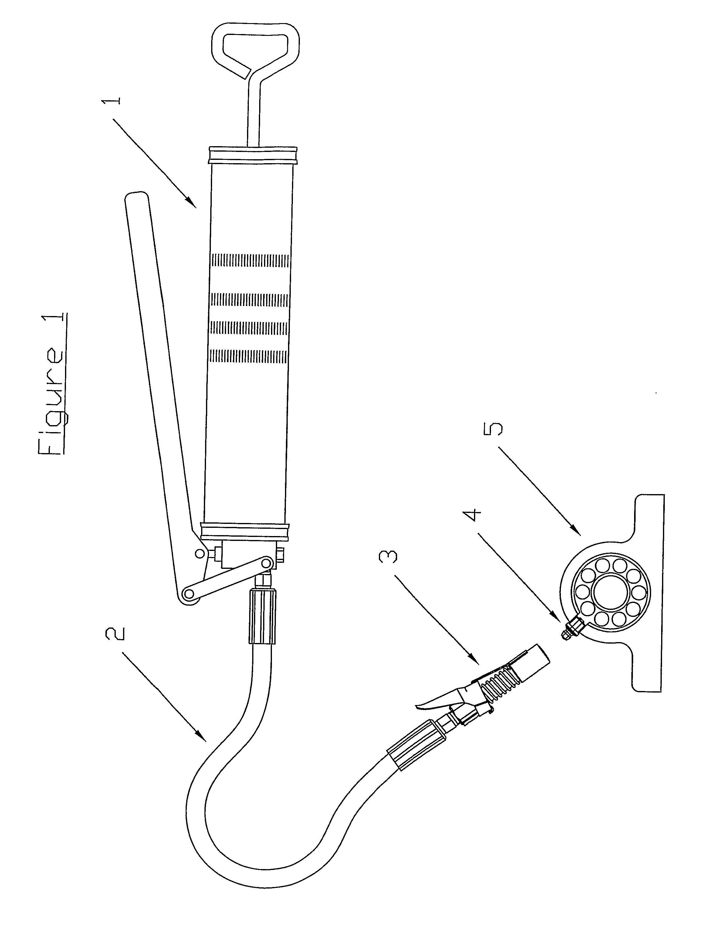
[0023]FIG. 1 depicts a general layout of a traditional type of greasing system with grease gun (1) delivering pressurised grease through delivery line (2) via the grease coupler (3) which engages zerk fitting (4) which is fixed to bearing / bush (5). The coupler forms a leak proof seal with zerk fitting. This layout depicts a manually operated hand grease gun with a flexible hose. There are many variants of grease dispensing units that can all utilise the common advantages of the improved coupler when connecting to a standard zerk fitting.

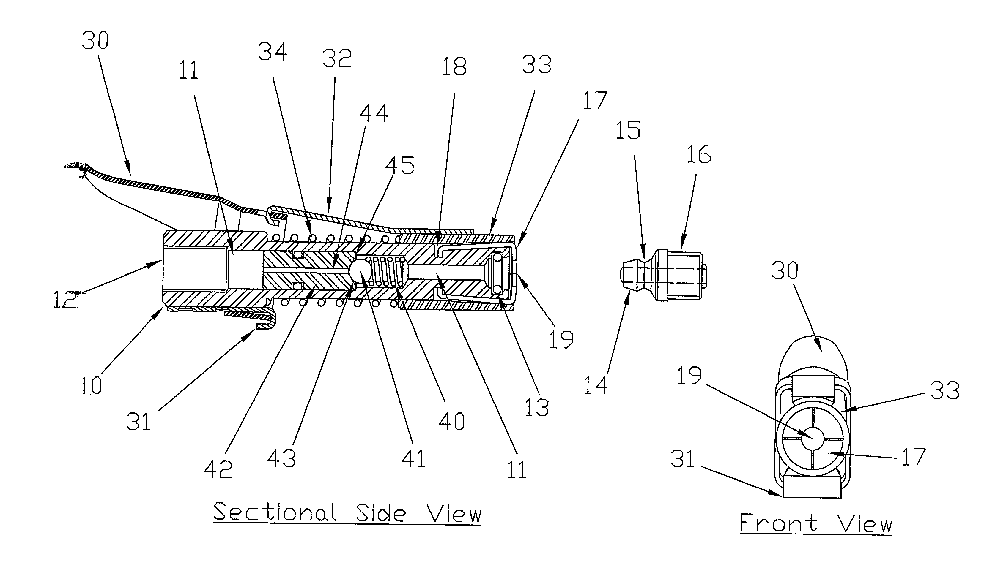
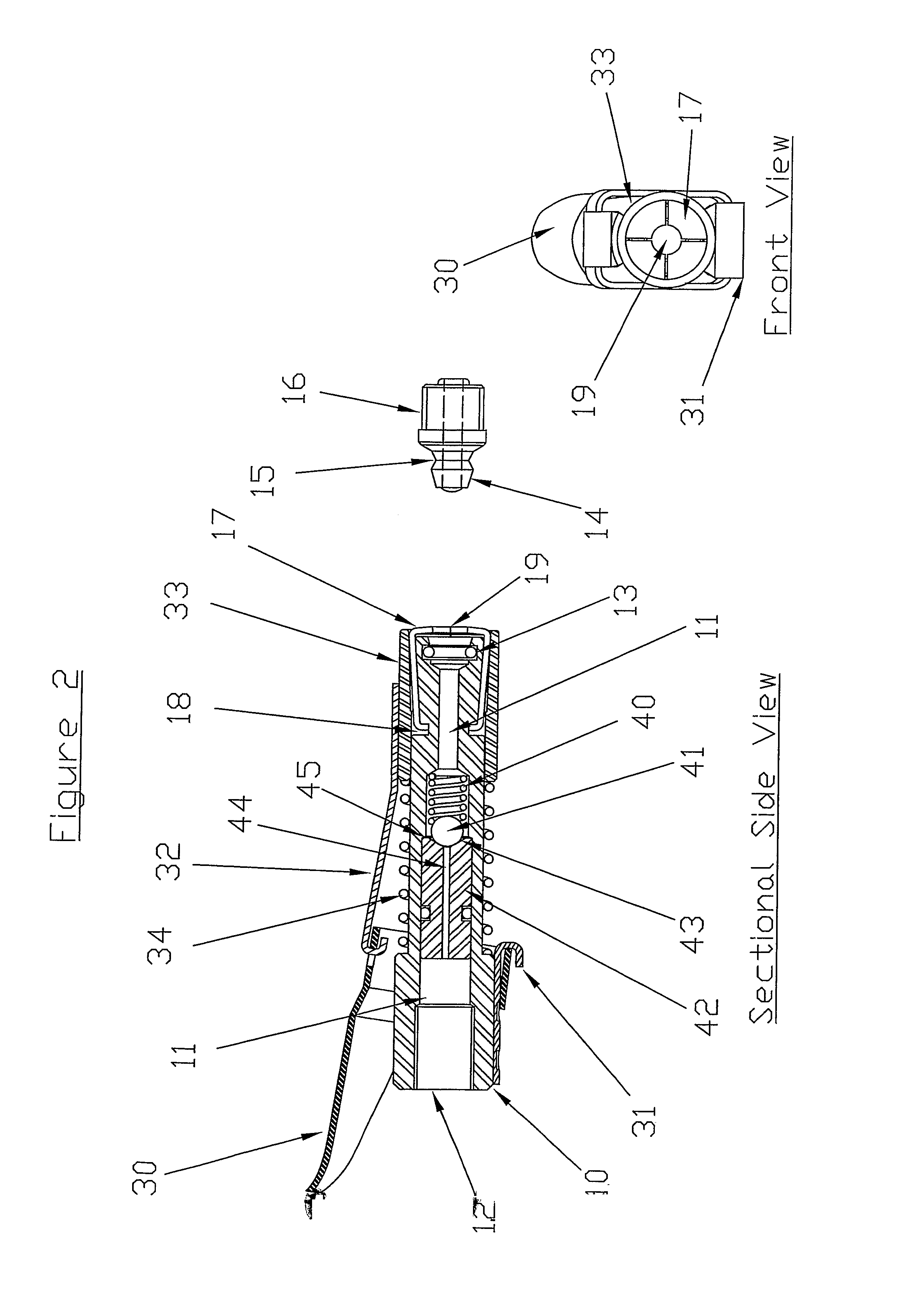
[0024]FIG. 2 depicts the preferred embodiment of the invention. Shown is the elongate body (10) with the passage (11) which runs through its full length and with inlet port (12) at the rear end of the body.

[0025]The easily replaceable seal (13) is situated at the discharge end of the elongate body where it seals on the outside of taper (14) of the zerk fitting (1...


PUM


Abstract

An improved grease coupler 3 allows for positive, coupling and uncoupling from a grease nipple 4 via a manually operated trigger mechanism 30. The coupler includes a replaceable seal 13 and has an elongate body 10 with a grease passage 11 through the length of the body. A floating barrel plunger 42 acts as a check valve to prevent grease leaking from the discharge end of the elongate body 10 upon disconnection.

Description

TECHNICAL FIELD OF THE INVENTION[0001]This invention relates to an improved apparatus for connecting the pressurized discharge from a grease gun to a standard Zerk type grease nipple.BACKGROUND ART[0002]The conventional Zerk coupler and Zerk nipple have remained virtually unchanged for well over 50 years. There are other types of couplers and nipples available on the market; however the Zerk type has become close to being the international standard.[0003]When connecting the standard Zerk coupler to a matching nipple, the coupler is pushed against the nipple, this force displacing the retaining jaws backwards against a spring tension into a conical cavity which allows the jaws to expand over the head of the nipple. On releasing this manual force the internal spring drives the jaws forward into the tapered chamber thereby clipping the jaws over the nipple head. The angles of the taper are of such a degree that the coupler can be easily pulled off the nipple at this stage. To prevent t...

Claims


Application Information

Patent Timeline
Patent Type & Authority Patents(United States)
IPC IPC(8): F16K15/00F16N21/00F01M11/04B65D25/40F16K21/04F16L21/06F16L37/138F16N3/12F16N21/02
CPCF16N3/12F16N21/02F16L37/138Y10T137/7927F16L37/121
Inventor GURNEY, RICHARD STILLARD
Owner GURTECH
Why Eureka
Try Eureka