Earphone

a technology for earphones and earphones, applied in the field of earphones, can solve the problem of excessive low frequency band characteristics

Active Publication Date: 2016-04-19
PANASONIC INTELLECTUAL PROPERTY MANAGEMENT CO LTD
View PDF22 Cites 18 Cited by
  • Summary
  • Abstract
  • Description
  • Claims
  • Application Information

AI Technical Summary

Benefits of technology

[0008]According to the present disclosure, an earphone having a space provided at a back surface of a loudspeaker unit can realize the sound pressure frequency characteristics suitable for the earphone by using two braking parts.

Problems solved by technology

However, when the loudspeaker unit having the reduced minimum resonance frequency is used in equipment such as earphones in which the loudspeaker unit is driven in a closed space surrounded by an eardrum and an external auditory canal, the low frequency band characteristics become excessive as compared to the high frequency band characteristics, and therefore, the sound pressure frequency characteristics need to be adjusted in some way.

Method used


Image

  • Earphone
  • Earphone
  • Earphone

Examples


embodiment 1

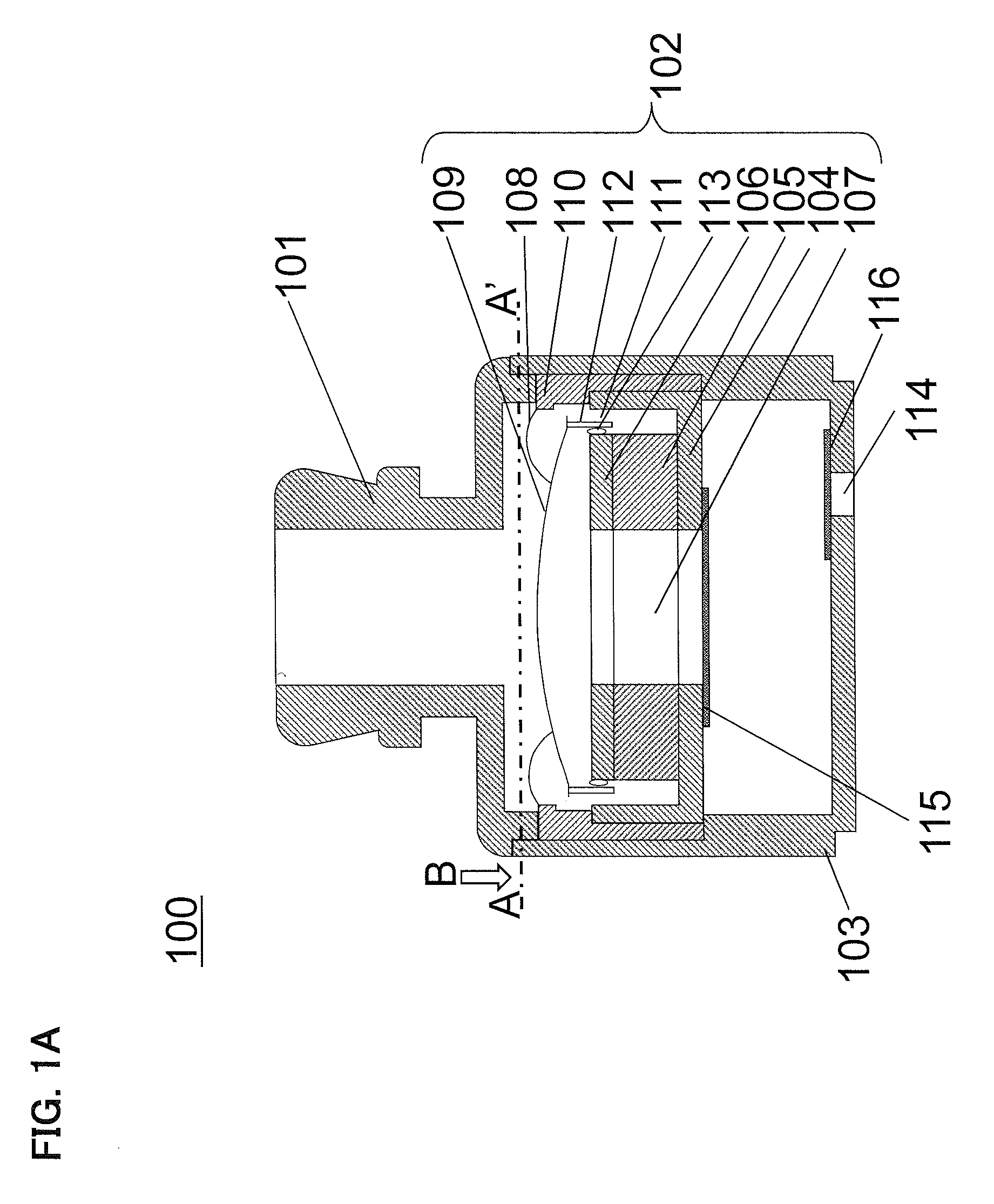
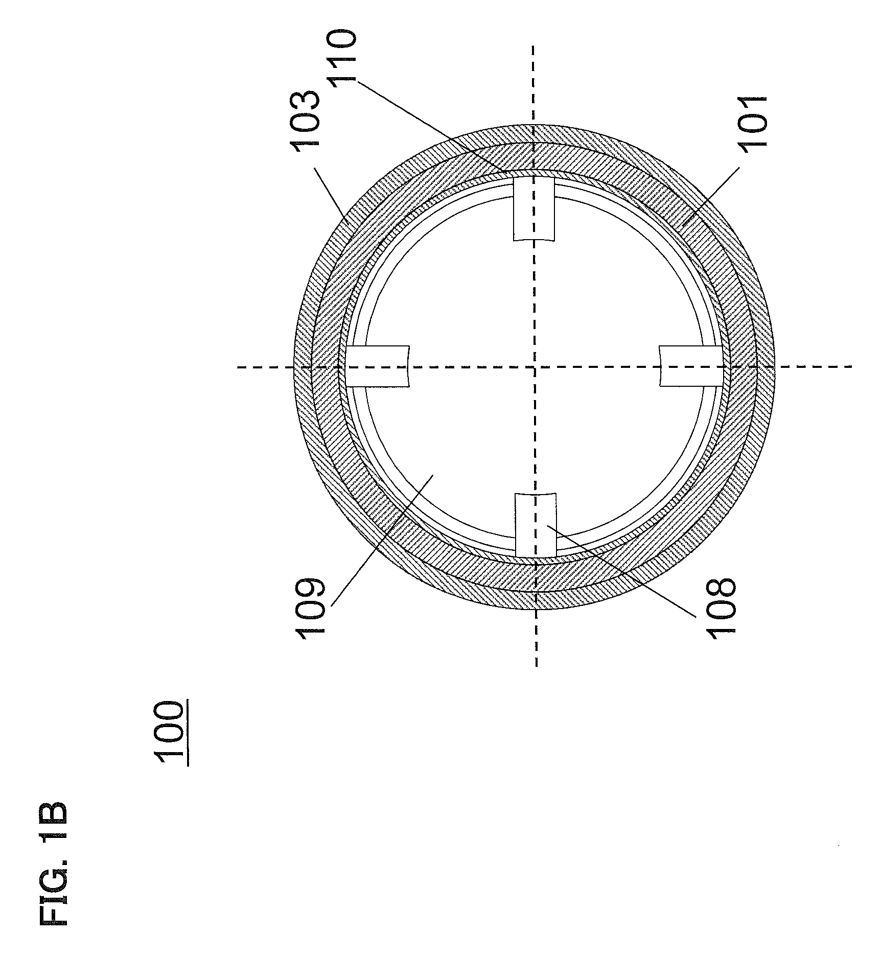
[0044]Hereinafter, Embodiment 1 will be described. Firstly, the configuration of an earphone 100 according to the present embodiment will be described. FIG. 1A is a schematic cross-sectional view of the earphone 100 according to the present embodiment. FIG. 1B is a schematic cross-sectional view taken along a line A-A′ in FIG. 1A and viewed in the direction of an arrow B. The earphone 100 includes a sound conductive tube 101, a loudspeaker unit 102, a housing 103, a first braking part 115, and a second braking part 116 joined to the housing 103. The loudspeaker unit 102 includes a yoke 104, a magnet 105, a plate 106, a sound hole 107, support members 108 each having an arch-shaped cross section, a diaphragm 109 supported by the support members 108, a frame 110 to which the support members 108 are joined, a magnetic gap 111 produced by the yoke 104 and the plate 106, a voice coil 112 held in the magnetic gap 111, and a magnetic fluid 113 that fills a space between the plate 106 and t...

embodiment 2

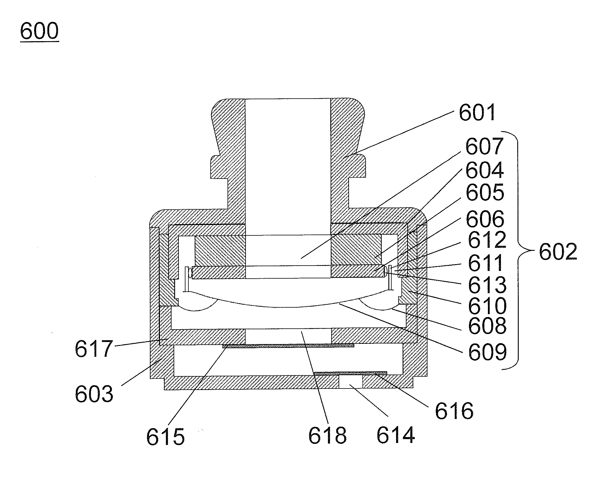
[0056]Hereinafter, an earphone 600 according to Embodiment 2 will be described. The earphone 600 is characterized by that, in the earphone 100 of the Embodiment 1, if the sound conductive tube 101 side is an upper side, the loudspeaker unit 102 is inverted so that the diaphragm 109 faces the bottom wall of the housing 103, and a back surface plate through which a second air hole is formed is provided inside the housing, and the first braking part is joined to the back surface plate so as to close the second air hole. FIG. 8 is a schematic cross-sectional view of the earphone 600 according to the present embodiment. The earphone 600 includes a sound conductive tube 601, a loudspeaker unit 602, a housing 603, a back surface plate 617, a first braking part 615 joined to the back surface plate 617 so as to close a second air hole 618 provided through the back surface plate 617, and a second braking part 616 joined to the housing 603 so as to close a first air hole 614 provided through t...

embodiment 3

[0060]Hereinafter, an earphone 800 according to Embodiment 3 will be described. The earphone 800 is characterized by that, in the earphone 600 of the Embodiment 2, the back surface plate 617 having the second air hole 618 and the first braking part 615 are not provided. FIG. 11 is a schematic cross-sectional view of the earphone 800 according to the present embodiment. The earphone 800 includes a sound conductive tube 801, a loudspeaker unit 802, a housing 803, and a second braking part 816 joined to the housing 803 so as to close a first air hole 814 provided through the housing 803. The loudspeaker unit 802 includes a yoke 804, a magnet 805, a plate 806, a sound hole 807, support members 808 each having an arch-shaped cross section, a diaphragm 809 supported by the support members 808, a frame 810 joined to the support members 808, a magnetic gap 811 formed by the yoke 804 and the plate 806, a voice coil 812 held inside the magnetic gap 811, and a magnetic fluid 813 that fills a s...


PUM


Abstract

An earphone includes: a loudspeaker unit; a sound conductive tube which is connected to a front surface having a diaphragm included in the loudspeaker unit, and has a hole through which a sound generated from the loudspeaker unit is emitted; a housing which is connected to a back surface of the loudspeaker unit so that a space is formed between the housing and the back surface of the loudspeaker unit, and has a first air hole connecting the space to external air; a first braking part which closes a sound hole of the loudspeaker unit; and a second braking part which closes the first air hole.

Description

TECHNICAL FIELD[0001]The present disclosure relates to earphones. More particularly, the present disclosure relates to earphones capable of adjusting sound pressure frequency characteristics.BACKGROUND ART[0002]In recent years, a small-size loudspeaker unit has been proposed, in which the minimum resonance frequency of the loudspeaker unit is reduced to several hundreds of Hz by using a magnetic fluid. In televisions and mobile phones, use of such a loudspeaker unit can increase the low frequency band characteristics, as compared to conventional loudspeaker units. However, when the loudspeaker unit having the reduced minimum resonance frequency is used in equipment such as earphones in which the loudspeaker unit is driven in a closed space surrounded by an eardrum and an external auditory canal, the low frequency band characteristics become excessive as compared to the high frequency band characteristics, and therefore, the sound pressure frequency characteristics need to be adjuste...

Claims


Application Information

Patent Timeline
Patent Type & Authority Patents(United States)
IPC IPC(8): H04R25/00H04R1/10H04R1/28H04R25/02H04R9/02
CPCH04R1/10H04R1/2811H04R25/02H04R25/48H04R1/1016H04R9/027
Inventor SAKAGUCHI, ATSUSHISAIKI, SHUJIMATSUMURA, TOSHIYUKIKANO, SAWAKOFUJISE, AKIKO
Owner PANASONIC INTELLECTUAL PROPERTY MANAGEMENT CO LTD
Why Eureka
Try Eureka