
Modulation for coded light transmission

a technology of coded light and module, applied in the field of coded light system, can solve the problems of difficult realization of circuits in cheap drivers of led light sources for such high frequencies, and achieve the effect of fast and accurate decoding

Active Publication Date: 2016-05-31
SIGNIFY HLDG BV
View PDF11 Cites 1 Cited by
  • Summary
  • Abstract
  • Description
  • Claims
  • Application Information

AI Technical Summary

Benefits of technology

The present invention provides methods, devices, and system concepts to improve the spectral confinement of coded light, particularly at low frequencies, while keeping the complexity of the system low. The invention achieves this by mapping each source symbol to a composite channel symbol, which results in a zero power spectral density at frequency zero of the control signal. This ensures no visible flicker in the emitted coded light. Additionally, the invention includes a processing unit that performs hard decision decoding to accurately determine the sequence of decoded source symbols. This enables fast and accurate decoding. Overall, the invention improves the quality and efficiency of coded light systems.

Problems solved by technology

It may also be desirable that the spectrum of the modulation code does not contain high frequencies for the reason that circuits in cheap drivers for an LED light source for such high frequencies may be difficult to realize.

Method used


Image

  • Modulation for coded light transmission
  • Modulation for coded light transmission
  • Modulation for coded light transmission

Examples


Embodiment Construction

[0028]The below embodiments are provided by way of example so that this disclosure will be thorough and complete, and will fully convey the scope of the invention to those skilled in the art. Like numbers refer to like elements throughout.

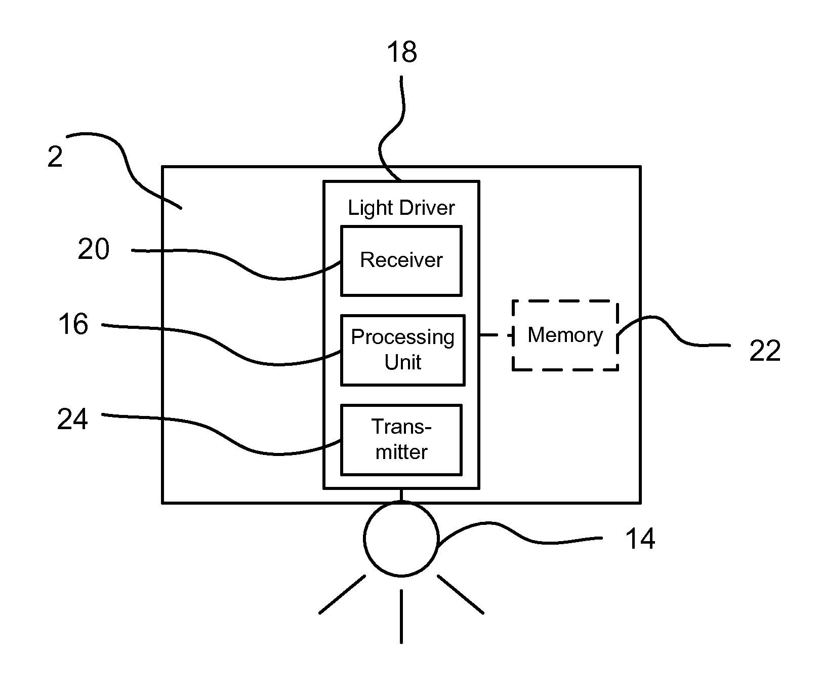
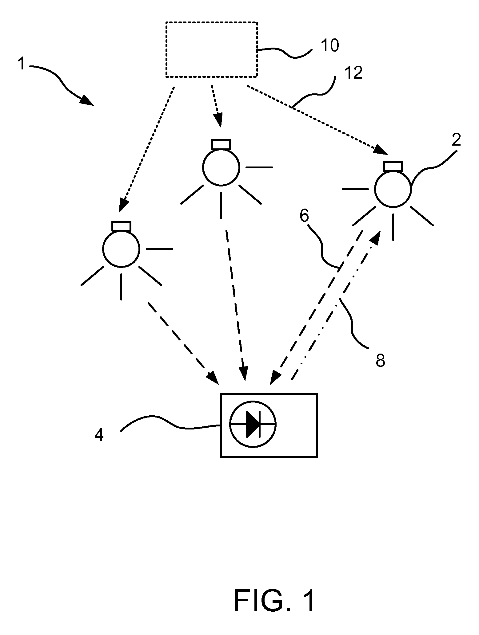
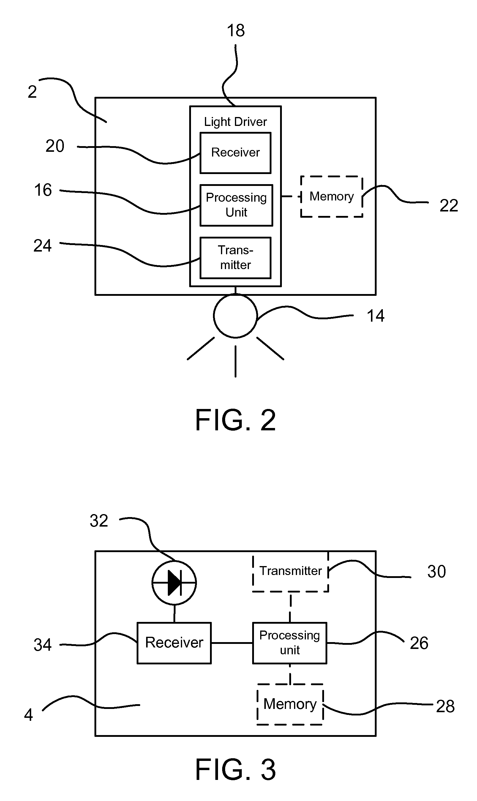
[0029]FIG. 1 illustrates a lighting system 1 comprises at least one light source, schematically denoted by the reference numeral 2. The at least one light source 2 may be a luminaire and / or be part of a lighting control system, thus the lighting system 1 may be denoted as a coded lighting system. A luminaire may comprise at least one light source 2. The term “light source” means a device that is used for providing light in a room, for purpose of illuminating objects in the room. A room is in this context typically an apartment room or an office room, a gym hall, a room in a public place or a part of an outdoor environment, such as a part of a street. Each light source 2 is capable of emitting coded light, as schematically illustrated by the arrow 6...


PUM


Abstract

Coded light has been proposed to enable advanced control of light sources and transmit information using light sources. Sequences of channel symbols to drive the light source are determined from sequences of source symbols such that no visible flicker is present in coded light emitted by the light sources. Each source symbol is mapped to a composite channel symbol comprising at least one first channel symbol which may be identical to the current source symbol and at least one second channel symbol which may be a function of the current source symbol and at least one future and / or past source symbol.

Description

FIELD OF THE INVENTION[0001]The present invention relates to a coded light system. Particularly it relates to methods and devices for driving at least one light source arranged to emit coded light in a coded light system and for decoding such coded light into an information sequence.BACKGROUND OF THE INVENTION[0002]Light sources are nowadays applied in lighting systems consisting of a large number of light sources. Since the introduction of solid state lighting several parameters of these light sources can be varied and controlled in a system of light sources. Such parameters include light intensity, light color, light color temperature and even light direction. By varying and controlling these parameters of the different light sources, a light designer or user of the system is enabled to generate lighting scenes. This process is often referred to as scene setting, and is typically quite a complex process due to the multitude of light sources and parameters to be controlled. Typical...

Claims


Application Information

Patent Timeline
Patent Type & Authority Patents(United States)
IPC IPC(8): H04B10/116H05B37/02
CPCH04B10/116H05B37/0272H05B47/195
Inventor RIETMAN, RONALDBAGGEN, CONSTANT PAUL MARIE JOZEFPENNING DE VRIES, HENDRICUS THEODORUS GERARDUS MARIA
Owner SIGNIFY HLDG BV
Learn More