Apparatus and methods for recovery of variational wind energy

a wind energy and variational technology, applied in the direction of machines/engines, electric generator control, greenhouse gas reduction, etc., can solve the problem of large inertial resistance, achieve the effect of increasing the electrical energy obtained, increasing the turbulence in the wind, and maximizing the electrical energy obtained

Inactive Publication Date: 2016-06-14
SANCHEZ JAMES MICHAEL +1
View PDF82 Cites 10 Cited by
  • Summary
  • Abstract
  • Description
  • Claims
  • Application Information

AI Technical Summary

Benefits of technology

[0018]The elastic member may have a force constant that is variable. The force constant of the elastic member may be tunable in response to the variable velocity of the wind, and, to the average wind velocity, enabling variational capture over a wide range of average wind velocities.
[0034]In certain embodiments, the elastic member may have a force constant that is variable, with the method further comprising controlling the force constant to maximize the electrical energy obtained from the apparatus.
[0037]The method may be further comprised of causing increased turbulence in the wind proximate to the wind receiving member, thereby changing the oscillating motion of the wind receiving member, and increasing the electrical energy obtained from the apparatus. The change in oscillating motion may be one or more of increasing amplitude of the oscillating motion, increasing frequency of the oscillating motion, increasing force of the oscillating motion, or changing direction of the oscillating motion.
[0038]The Applicants have developed certain numerical analytical methods that enable rational decision making with regard to whether there is sufficient recoverable wind energy from wind velocity variation at a particular site. The Applicants' methods allow a determination that placement of the Applicants' apparatus at a particular site is justifiable in advance of such placement, instead of incurring the cost of apparatus fabrication, transportation, and installment, without knowledge that there is sufficient recoverable wind energy from wind velocity variation for the apparatus to perform its intended overall function, and to do so at a lower cost and in a more reliable manner than other alternatives.

Problems solved by technology

The large mass nature of most bladed wind recovery systems results in large inertial resistance to rapid wind velocity, or density, changes.

Method used


Image

  • Apparatus and methods for recovery of variational wind energy
  • Apparatus and methods for recovery of variational wind energy
  • Apparatus and methods for recovery of variational wind energy

Examples


Embodiment Construction

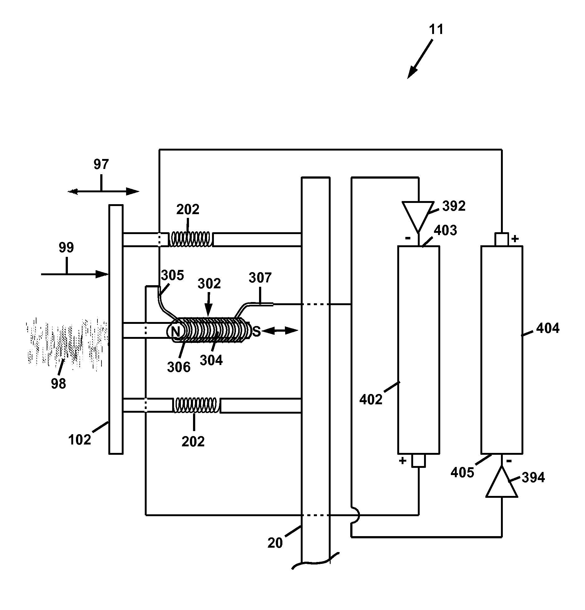
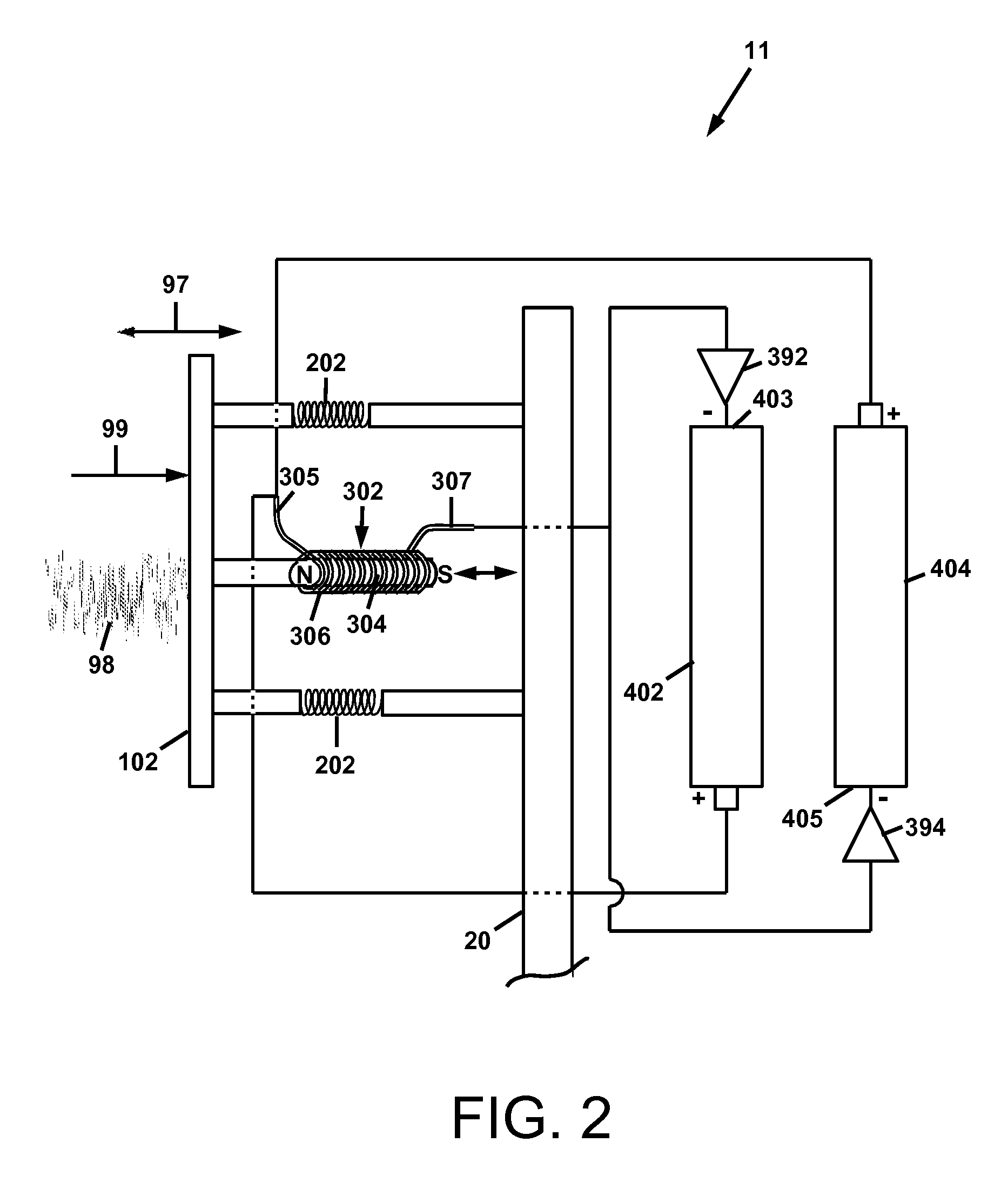
[0062]For a general understanding of the present invention, reference is made to the drawings. In the drawings, like reference numerals have been used throughout to designate identical elements. As used herein, the acronym “VWER” is meant to indicate “variable wind energy recovery,”, e.g., in reference to a VWER apparatus and a VWER method.

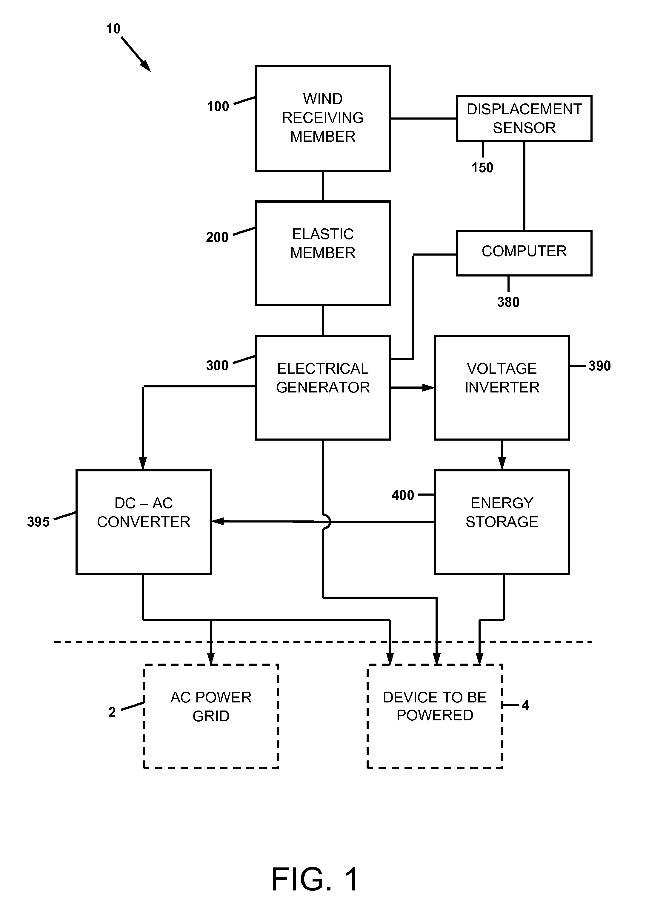
[0063]Turning first to FIG. 1, a block diagram of an apparatus for recovery of variational wind energy is depicted. The apparatus 10 is comprised of a first wind receiving member 100 displaceable by a wind having a variable velocity, a first elastic member 200 coupled to the first wind receiving member, and an electrical generator 300 operatively connected to the first wind receiving member 100 and configured to convert mechanical energy of the first wind receiving member 100 to electrical energy.

[0064]The apparatus 10 may be further comprised of an energy storage device 400 in communication with the electrical generator 300. In certain embodiment...


PUM


Abstract

A wind energy recovery apparatus and related methods are disclosed. The apparatus is comprised of a first wind receiving member displaceable by a wind having a variable velocity, a first elastic member coupled to the first wind receiving member, and an electrical generator operatively connected to the first wind receiving member and configured to convert mechanical energy of the first wind receiving member to electrical energy. An energy storage device may be provided in communication with the electrical generator. A self-powered signal communications system including the apparatus is also disclosed. A method of identifying a site for recovering variational wind energy is also disclosed.

Description

CROSS-REFERENCE TO RELATED PATENT APPLICATIONS[0001]This application claims priority from U.S. provisional patent Application No. 61 / 864,560 filed Aug. 10, 2013, the disclosure of which is incorporated herein by reference.BACKGROUND[0002]1. Technical Field[0003]Renewable energy sources, and more particularly, recovery of energy from wind.[0004]2. Description of Related Art[0005]Wind energy recovery has a long history spanning many centuries. The uses for recovered wind energy include the milling grain, pumping water from sources, transferring water between source and use locations, and, more recently, the generation of alternating current electrical power.[0006]In spite of recent progress in alternative energy technologies such as solar energy and wind energy, there remains a need for further improvement in these technologies in order to make them economically viable as compared to current energy sources such as fossil fuels and nuclear power. This has become even more evident with ...

Claims


Application Information

Patent Timeline
Patent Type & Authority Patents(United States)
IPC IPC(8): B60L11/12F03D9/00F03D5/06H02N2/18H02P9/04F02B63/04H02J7/34B60L50/15
CPCF03D15/00F03D5/06F03D9/002F03D9/10H02J7/34H02N2/185F05B2220/707F05B2260/40F05B2260/407H02J7/345Y02E10/70Y02E10/722Y02E10/725Y02E10/766F03D9/11F03D9/25H02J2300/28Y02E10/72Y02E10/76Y02E70/30
Inventor SANCHEZ, JAMES MICHAELHAMMOND, JOHN M.
Owner SANCHEZ JAMES MICHAEL
Why Eureka
Try Eureka