Process and system employing phase-changing absorbents and magnetically responsive sorbent particles for on-board recovery of carbon dioxide from mobile sources

a technology of phase-changing absorbents and magnetically responsive sorbent particles, applied in the direction of separation processes, machines/engines, mechanical equipment, etc., can solve the problems of space and weight limitations, lack of any economies of scale, and more difficult if attempted, so as to reduce co2 emissions, maximize the electrical energy generating value of fuel, and reduce the effect of waste heat at high to moderate temperatur

Active Publication Date: 2015-11-03
SAUDI ARABIAN OIL CO
View PDF4 Cites 13 Cited by
  • Summary
  • Abstract
  • Description
  • Claims
  • Application Information

AI Technical Summary

Benefits of technology

[0018]One advantage of the present invention over prior art processes for reducing CO2 emissions from fixed sources such as power generation facilities is the ready availability on board the mobile source of relatively high to moderate temperature waste heat. The cost of the heat energy is a major item of expense for CO2 capture from fixed sources because the temperature of the flue gases from a coal-fired or gas-fired electric power generation facility has been reduced in order to maximize the electrical energy generating values of the fuel and to minimize the amount of waste heat discharged into the environment. Flue gas temperature reduction is also important for capturing sulfur oxides (SOx) and nitrogen oxides (NOx) as pollutants in power plants that burn sulfur-containing fuels.
[0019]The waste heat that a typical engine produces consists mainly of hot exhaust gases that can range in temperature from ˜300° C. to 650° C. and hot coolant ranging from about 80° C. to 120° C. This heat energy totals about 60-75% of the total energy that typical hydrocarbon fuels produce upon combustion in an ICE. The engine block, intake and exhaust manifolds, transmission housing, parts and fluid, as well as associated metal components are sources of this heat.
[0020]Energy is needed to separate the CO2 from the exhaust gases and to compress, liquefy or freeze all or part of the captured CO2 for efficient on-board storage. This energy is typically a mix of work and heat energies. The work component of the energy is generated by using part of the waste heat to produce this work. Some waste heat can be used by direct heat exchange to regenerate the sorbent capture materials used in the CO2 separation step of the process.
[0021]The present invention solves the problems of space limitations and auxiliary power requirements by using the free energy that is available on board the vehicle as waste heat to capture CO2 and increase its density for temporary storage until the vehicle is refueled, or otherwise can discharge the pressurized CO2 gas or liquid, or the cold solid CO2 for permanent storage. The use of the waste heat to provide the energy for capture, regeneration and densification significantly reduces the capture cost and the densification will reduce the volume requirement for temporary on-board storage of the CO2. Converting the waste heat into electrical or other useable forms of work energy also reduces or eliminates the amount of fuel that is consumed by the vehicle in contributing mechanical energy for the densification step, and thereby a corresponding reduction in the amount of CO2 in the exhaust gas stream.
[0022]The increase in the density of the captured CO2 for efficient on-board temporary storage is accomplished by compression, liquefaction, or by freezing the gas to form solid CO2, i.e., dry ice. The final density of the CO2 will be in the range of from 5-1600 kg / m3, depending upon its state, i.e., gas, liquid and / or solid. At least a part of the total work energy required for the densification is obtained from the waste heat by using heat-to-power conversion.
[0023]During start-up of the CO2 capture cycle, or to meet a temporary requirement of other special operational needs of the vehicle, part of the engine's power or, alternatively, the electricity stored in on-board batteries can be used. During the normal operation of the system, at least a portion of the energy required for CO2 capture and densification will come from conversion of the ICE's waste heat into, e.g., electrical energy.

Problems solved by technology

CO2 management from mobile sources presents many challenges including space and weight limitations, the lack of any economies of scale and the dynamic nature of the operation of the ICEs powering the mobile sources.
Those that address the problem of reducing CO2 emissions from mobile sources employ either combustion using oxygen, provide no means for the regeneration and reuse of the CO2 capture agent, and / or make no use of waste heat recovered from the hot source.
Combustion using oxygen requires an oxygen-nitrogen separation step which is more energy-intensive than separating CO2 from the exhaust gases and would be more difficult if attempted on board the vehicle.
Thus, the high temperature of the ICE exhaust gas makes direct treatment to remove CO2 with liquid amine solutions impractical without cooling the exhaust gas.
The capture of CO2 from mobile sources has generally been considered too expensive, since it involves a distributed system with a reverse economy of scale.
The prior solution to the problem has appeared to be impractical due to on-board vehicle space limitations, the additional energy and apparatus requirements and the dynamic nature of the vehicle's operating cycle, e.g., intermittent periods of rapid acceleration and deceleration.

Method used


Image

  • Process and system employing phase-changing absorbents and magnetically responsive sorbent particles for on-board recovery of carbon dioxide from mobile sources
  • Process and system employing phase-changing absorbents and magnetically responsive sorbent particles for on-board recovery of carbon dioxide from mobile sources
  • Process and system employing phase-changing absorbents and magnetically responsive sorbent particles for on-board recovery of carbon dioxide from mobile sources

Examples


Embodiment Construction

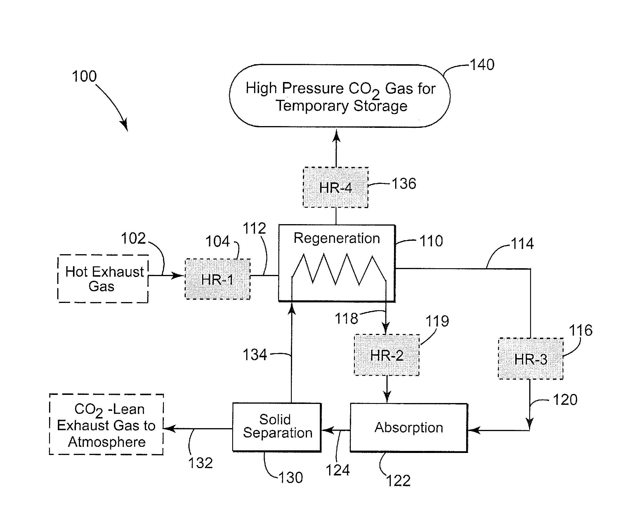
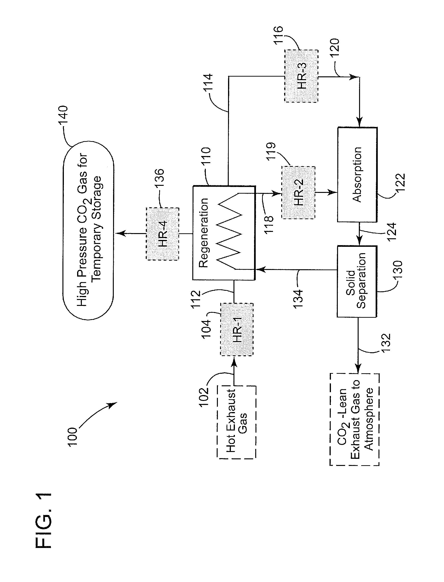
[0079]The invention will be further described in more detail with reference to FIG. 1 which illustrates an embodiment of a system and apparatus 100 for the practice of a CO2 absorption process which uses a chemical phase-changing sorbent. System 100 includes a regeneration zone 110, a chemical absorption / adsorption zone 122, a solid separation unit 130 and several heat recovery (HR) units as described in more detail below. In this description, it will be understood that each of the zones identified can contain one or more corresponding unit operations with one or more known pieces of apparatus which accomplish the functions and steps in the practice of the process of the invention.

[0080]Chemical sorbents such as liquid di-amines and other liquids functionalized with amine groups that form a reversible chemical bond with CO2 as described above can be used in the process of the invention. An example of a suitable chemical sorbent is liquid GAP-0 carbamate which reversibly reacts with ...


PUM

PropertyMeasurementUnit
temperaturesaaaaaaaaaa

Abstract

A method and system are described for the on-board treatment of a hydrocarbon-fueled internal combustion engine (ICE) exhaust gas stream to reduce CO2 emissions from the vehicle which include:a. contacting the exhaust gas stream with a CO2 sorbent capture agent on board the vehicle to produce a mixture containing modified CO2-containing sorbent and a treated exhaust gas stream with reduced CO2 content;b. separating the modified CO2-containing sorbent from the treated exhaust gas stream;c. passing the modified sorbent in heat exchange with heat from the ICE to release CO2 and regenerate the CO2 sorbent capture agent;d. recycling the regenerated CO2 sorbent for use in step (a);e. discharging the treated exhaust gas stream having a reduced CO2 content into the atmosphere;f. recovering and compressing the CO2 for temporary storage on board the vehicle.

Description

RELATED APPLICATIONS[0001]This application claims priority to provisional patent application U.S. Ser. No. 61 / 682,850 filed Oct. 5, 2012 and U.S. Ser. No. 61 / 715,933 filed Oct. 19, 2012, the contents of which are incorporated herein by reference.BACKGROUND OF THE INVENTION[0002]1. Field of the Invention[0003]The present invention relates to the reduction of carbon dioxide emissions from the exhaust gas stream of vehicles powered by internal combustion engines and other heat engines that produce waste heat.[0004]2. Description of Related Art[0005]The currently accepted thinking is that global warming is due to emissions of greenhouse gases such as carbon dioxide (CO2) and methane (CH4). About a quarter of global CO2 emissions are currently estimated to come from mobile sources, i.e., automobiles, trucks, buses and trains that are powered by internal combustion engines (ICEs). This proportional contribution is likely to grow rapidly in the foreseeable future with the projected surge i...

Claims


Application Information

Patent Timeline
Patent Type & Authority Patents(United States)
IPC IPC(8): B01D53/92F01N3/08F01N3/04B01D53/96B01D53/62B01D53/80B01D53/78B01D53/83
CPCF01N3/0857B01D53/62B01D53/80B01D53/92B01D53/78B01D53/83B01D2251/402B01D2251/404B01D2251/602B01D2251/606B01D2252/2041B01D2252/30B01D2253/102B01D2253/108B01D2253/204B01D2257/504B01D2259/4566B01D2259/65B01D2259/814Y02C10/04Y02A50/20Y02C20/40
Inventor HAMAD, ESAM ZAKI
Owner SAUDI ARABIAN OIL CO
Why Eureka
Try Eureka