Stimulation and injection system

a technology of injection system and injection tube, which is applied in the direction of fluid removal, insulation, borehole/well accessories, etc., can solve the problems of system failure and inability to operate, and achieve the effect of increasing efficiency

Inactive Publication Date: 2007-03-15
UNITED ENERGY CORP
View PDF4 Cites 4 Cited by
  • Summary
  • Abstract
  • Description
  • Claims
  • Application Information

AI Technical Summary

Benefits of technology

[0004] This invention is an improvement over the prior art. It utilizes a configuration which can allow generated vapor-containing stream to bypass the well and be released to the atmosphere. An injection system for injection of water is included to moderate the temperature at the injection site or in the injected sites. The strength (%) of the hydrogen peroxide solution can be used to control or vary pressure and heat. Increased efficiency is obtained by pre-heating the catalyst screen and using, for example, a silver screen coated with samarium oxide. The system also allows injection of treatment chemicals along with the vapor-containing stream.

Problems solved by technology

The system is fail-safe and cannot be operated until the gas generator has reached temperatures 350° F. and above.

Method used


Image

  • Stimulation and injection system
  • Stimulation and injection system

Examples


Embodiment Construction

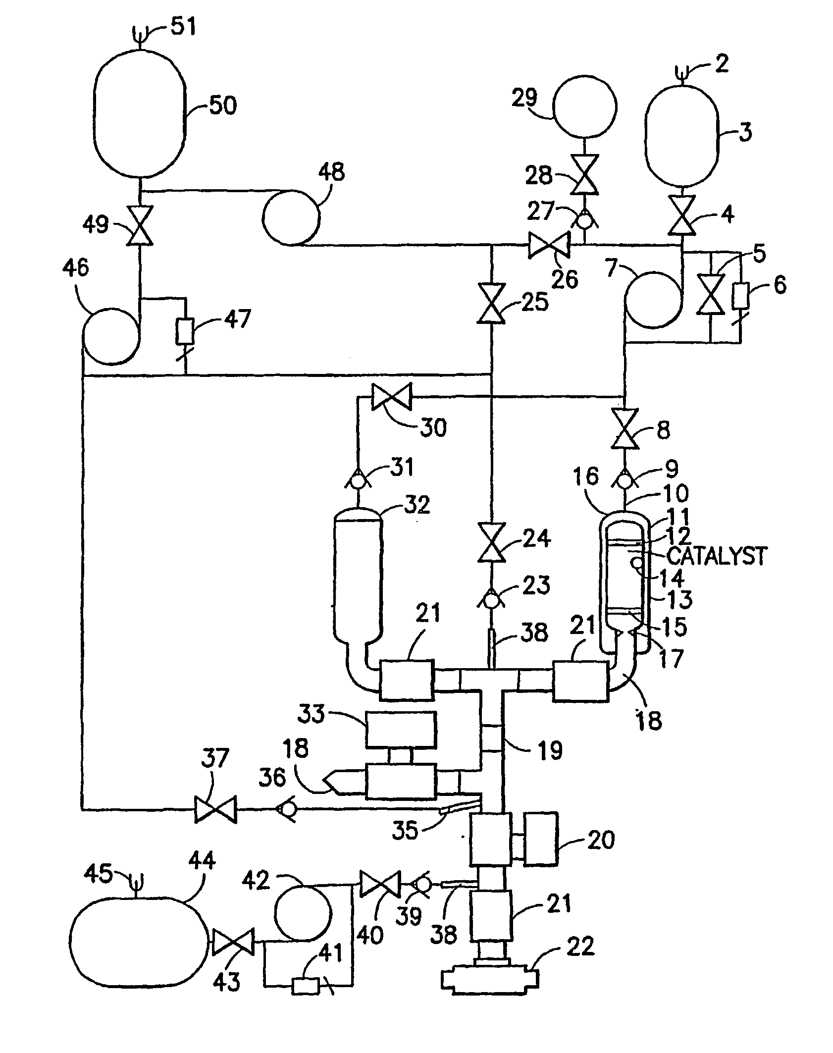
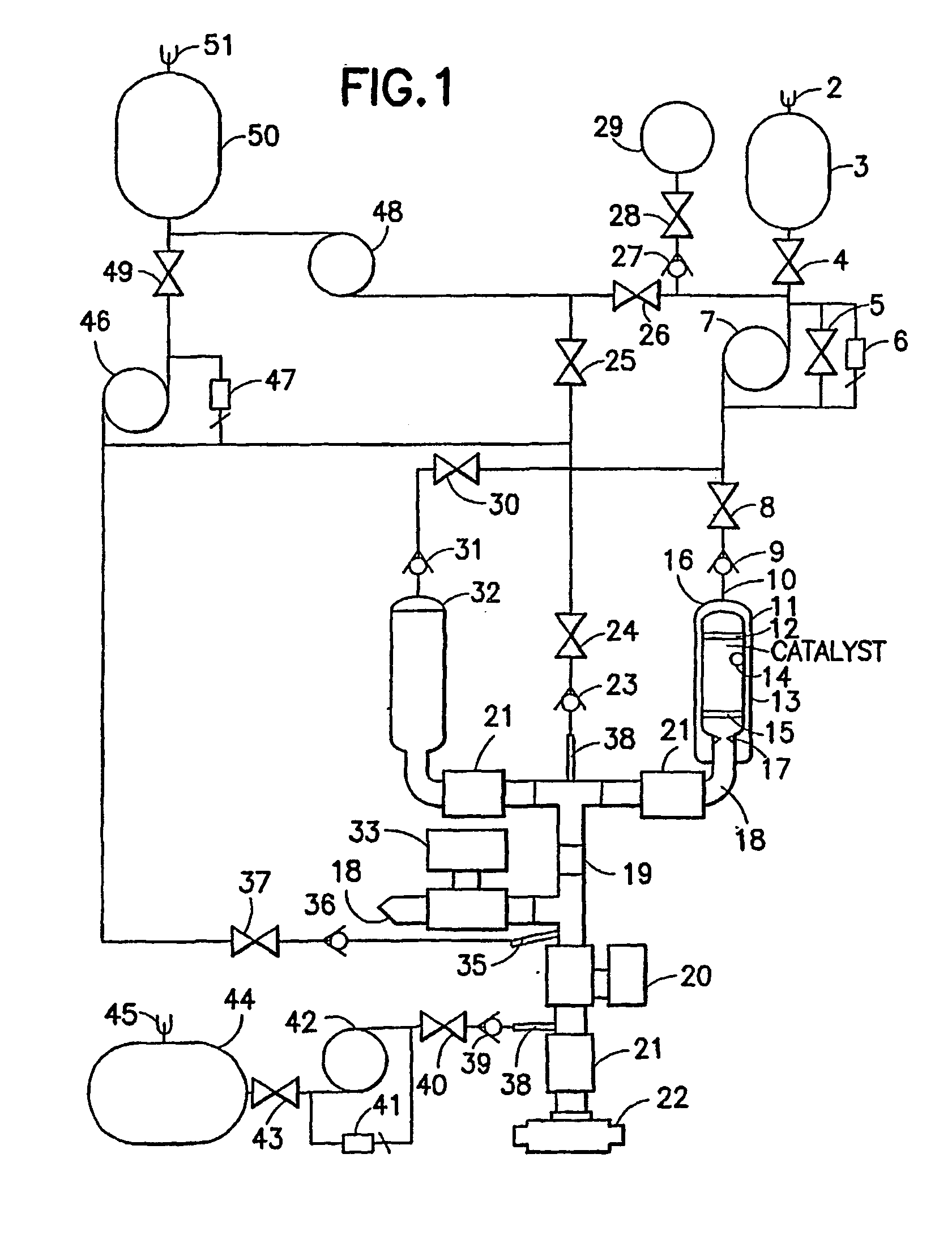
[0008] The present invention is directed to a system utilizing at least one vapor-containing stream generator to produce and inject a vapor-containing stream which can comprise steam, heated water, heated gas, and / or chemicals into underground formations, pumps, conduits or tanks. The system uses a vapor-containing stream drive with variable pressure and temperature, a steam drive with variable pressure and temperature, and chemical injection at variable pressures and temperature, which allows custom tailored cyclic drives.

[0009] The injection system has many applications due to the ability to inject heated vapor-containing streams at various temperatures and pressures. The injection system is ideal for solving paraffin problems as well as a heavy crude and gas depleted formations as well as in pumps, conduits or tanks. In addition the system is environmentally clean and easy to operate.

[0010] The pumps and vapor-containing stream generator and generator are present in a single lo...


PUM


Abstract

An apparatus for introducing a vapor-containing stream into underground geological formations, pumps, conduits or tanks comprising; at least one vapor-containing stream generator having a liquid hydrogen peroxide fuel introduction zone, a catalyst zone and a zone for creating a backpressure of a vapor-containing stream formed by the generator; a conduit for introducing the liquid hydrogen peroxide fuel with said liquid hydrogen peroxide having a concentration of from 7095 weight percent into the vapor-containing stream generator; means for directing the vapor-containing stream into the formation, pump, conduit or tank and means for introducing a fluid into the formations, pumps, conduits or tanks.

Description

FIELD OF THE INVENTION [0001] The invention relates to a system for injection of a vapor-containing stream and chemicals into underground formations, pumps, conduits or tanks. BACKGROUND OF THE INVENTION [0002] Previous technologies have attempted to recover oil by injecting hydrogen peroxide into the formation and allowing uncontrolled decomposition and heating. This often resulted in down hole fires and damage to equipment. [0003] One improvement to the direct injection of hydrogen peroxide was made by utilizing an in line vertical steam generator that could be used to cap the well head. The decomposition of hydrogen peroxide and silver mesh generated steam and oxygen, which were directly injected into the formation. Problems with this system occurred due to an inability to precisely control temperature and pressure, which resulted in damage to formations and well heads. BRIEF SUMMARY OF THE INVENTION [0004] This invention is an improvement over the prior art. It utilizes a config...

Claims


Application Information

Patent Timeline
Patent Type & Authority Applications(United States)
IPC IPC(8): E21B43/24E21B36/00E21B37/06E21B43/243
CPCC09K8/592E21B43/243E21B43/166E21B37/06
Inventor MILLER, SAMUEL
Owner UNITED ENERGY CORP
Why Eureka
Try Eureka