Delay water outlet valve for pipe-in-pipe and hot water discharge system thereof

A technology of pipe-in-pipe and water outlet valve, which is applied in the direction of valve operation/release device, valve details, multi-way valve, etc., which can solve the problems of affecting the service life of springs, unsuitable water pipes, and unsuitable pipe-in-pipe medium, etc., to reduce Effect of waste, ease of operation, protection of equipment and discharge system

Pending Publication Date: 2020-08-18
陈奎宏
View PDF1 Cites 3 Cited by
  • Summary
  • Abstract
  • Description
  • Claims
  • Application Information

AI Technical Summary

Problems solved by technology

[0007] 1. This structure is only suitable for single-channel delayed discharge, not suitable for application in tube-in-tube;
[0008] 2. The liquid outlet hole of this structure is set on the piston, which is only suitable for a small amount of liquid, not suitable for application in wa

Method used


Image

  • Delay water outlet valve for pipe-in-pipe and hot water discharge system thereof
  • Delay water outlet valve for pipe-in-pipe and hot water discharge system thereof
  • Delay water outlet valve for pipe-in-pipe and hot water discharge system thereof

Examples


Example Embodiment

[0066] Example one:

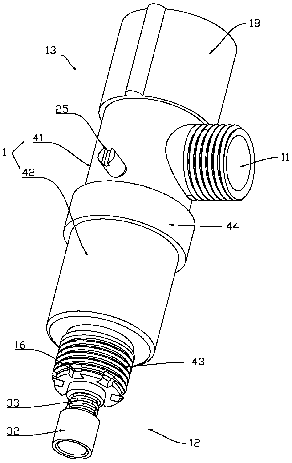
[0067] Such as Figure 1-3 As shown, a delayed water outlet valve for a pipe-in-pipe includes a valve body 1. The valve body 1 is provided with a liquid outlet end 11, a control end 13, and a pipe-in-pipe connection end 12, the pipe-in-pipe connection end 12 Generally, it is installed on the pipe-in-pipe pipe through a pipe-in-pipe joint, and realizes the delayed discharge of the pipe-in-pipe pipe. A control end 13 is provided between the pipe-in-pipe connection end 12 and the liquid outlet end 11. The control end 13 is provided with a control valve core 17 and a handwheel 18 that drives the control valve core 17 to rotate. The valve core 17 is common on the market The ceramic valve core, ball head valve core, etc., are driven by the handwheel 18 to achieve liquid discharge control. In addition, in order to achieve the same control effect, the liquid outlet 11 may be connected to an external control valve.

[0068] In order to facilitate the installation of ...

Example Embodiment

[0078] Example two

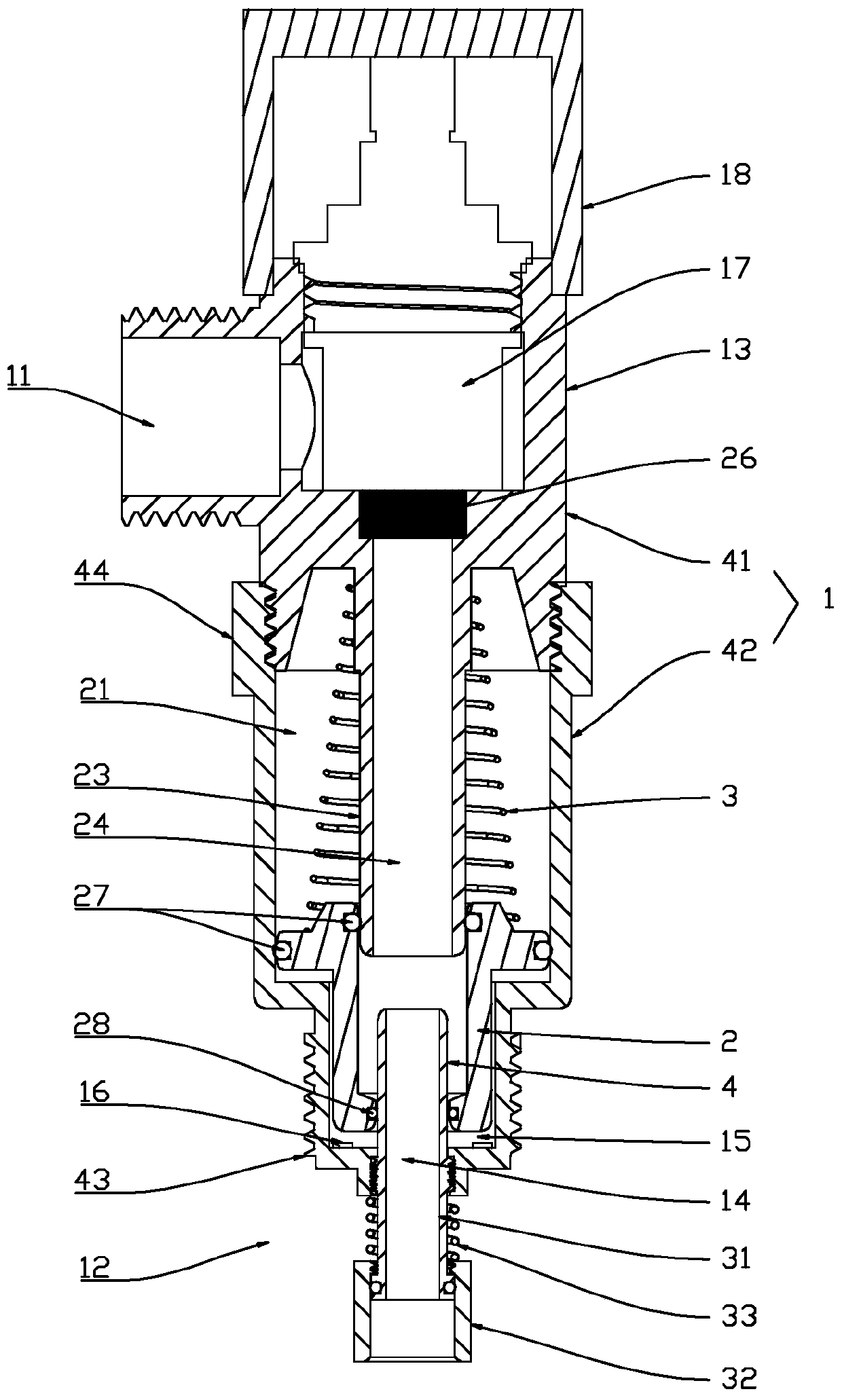
[0079] Such as Figure 4-6 As shown, this embodiment is basically the same as the first embodiment. The difference is that the piston guide rod 23 is separately arranged in the integrally formed valve body 1. Specifically, the piston guide rod 23 is axially opened with an intermediate flow The upper end of the channel 24 is provided with a mounting flange, the upper end of the mounting flange abuts against the through hole of the valve body 1 and the lower end abuts the first reset member 3. The other end of the first reset member 3 abuts against the damping piston 2, the sealing end of the damping piston 2 is provided with at least one return hole 52, and a water return sheet 53 is provided on the outside of the return hole 52. When the pressure of the inner flow channel is relatively high, the pressure relief and return flow can be achieved through the return hole 52.

[0080] Preferably, the damping adjustment channel of this embodiment is provided with a d...

Example Embodiment

[0082] Example three

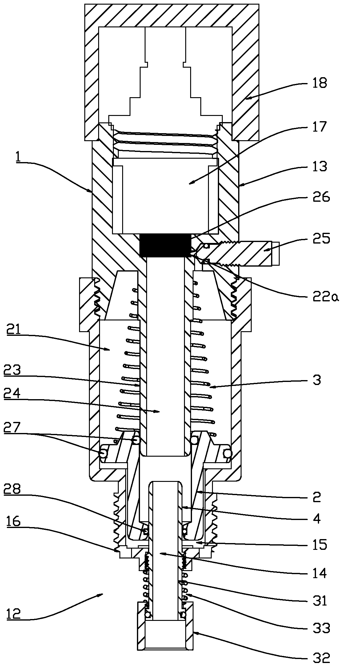
[0083] Such as Figure 7-9 As shown, this embodiment is basically the same as the first embodiment. The difference is that the piston guide rod 23 is separately arranged in the integrally formed valve body 1. Specifically, the piston guide rod 23 is axially opened with an intermediate flow The upper end of the channel 24 is provided with a mounting flange, the mounting flange is installed on the step surface of the valve body through the valve core, and a sealing gasket is provided between the mounting flange and the valve core. The lower end of the piston guide rod 23 is outwardly provided with a sliding convex ring, and the sliding convex ring is provided with a damping adjustment hole 22a. The sliding convex ring reduces the friction force by reducing the contact area with the damping piston 2; at the same time, the sliding convex ring can form a gap between the damping piston 2 and the piston guide rod 23 to facilitate the damping adjustment hole 22a to...


PUM


Abstract

The invention belongs to the technical field of domestic water, and particularly relates to a delay water outlet valve for a pipe-in-pipe and a hot water discharge system thereof. The delay water outlet valve for the pipe-in-pipe comprises a water heater, a liquid inlet valve and a pipe-in-pipe pipeline, the delay water outlet valve is arranged at the tail end of a branch of a pipe-in-pipe pipeline through a pipe-in-pipe joint, the delay water outlet valve comprises a valve body, the valve body is provided with a liquid outlet end and a pipe-in-pipe connecting end, the pipe-in-pipe connectingend is provided with an inner flow passage and an outer flow passage, and the liquid outlet end communicates with the inner flow passage and the outer flow passage through an inner cavity of the valvebody; the inner side of the pipe-in-pipe connecting end is provided with a delay sealing part separating the inner flow passage and the outer flow passage, the inner cavity of the valve body is provided with a damping piston and a first reset part providing elastic force, the damping piston is arranged on the outer side wall or the inner side wall of the delay sealing part, and the outer flow passage or the inner flow passage is sealed; and when an internal medium pushes the damping piston to separate the delay sealing part, the delay liquid outlet of the flow passage where the damping pistonis located is realized. The delay water outlet valve for the pipe-in-pipe and the hot water discharge system thereof have the advantages of small cold water emptying amount, high hot water outlet speed and the like.

Description

Technical field [0001] The invention belongs to the technical field of domestic water, and particularly refers to a delayed water outlet valve used in a pipe-in-pipe and its hot water discharge system. Background technique [0002] The pipe-in-pipe pipe is composed of pipe-in-pipe and pipe-in-pipe joints, both of which are composed of a pipe-in-pipe inner tube forming an inner flow passage and a pipe-in-pipe outer pipe forming an outer flow passage. It has the advantages of convenient installation and fast liquid discharge speed. advantage. [0003] The utility model patent with the application number CN201820054377.9 discloses a hot water circulation system, which includes a water heater, a circulation pump, a non-return type starting valve, a hot water pipe composed of a hot water pipe and a pipe joint, And the tail valve for connecting external equipment. The liquid inlet end of the circulating pump is connected to the output end of the water heater, and the output end is conn...

Claims


Application Information

Patent Timeline
IPC IPC(8): F16K11/22F16K17/168F16K31/363F16K31/68F24H9/00F24H9/20
CPCF16K11/22F16K17/168F16K31/363F16K31/002F24H9/2007F24H9/0005
Inventor 陈友苗陈奎宏
Owner 陈奎宏
Why Eureka
Try Eureka