Converting Process with Partial Pre-Oxidation of PGM Collector Alloy

a technology of collector alloy and converting process, which is applied in the direction of process efficiency improvement, manufacturing converters, recycling and recovery technologies, etc., can solve the problems of significant loss, low conversion efficiency, and limited application prospects, so as to reduce the volume of converter slag, reduce alloy melting time, and increase conversion capacity and/or throughput

Active Publication Date: 2019-10-31
TECHEMET LP
View PDF0 Cites 5 Cited by
  • Summary
  • Abstract
  • Description
  • Claims
  • Application Information

AI Technical Summary

Benefits of technology

[0008]The present disclosure is directed to a converting process for recovering platinum group metals (“PGM”) that addresses drawbacks of known converting processes. Applicant has observed that the high levels of added flux materials comprising more than 10 wt % CaO / MgO and 10 wt % SiO2 in known PGM collector alloy converting processes can be reduced or avoided in the converting processes disclosed herein, and that limiting the amount of such flux in this manner leads to a reduced volume of converter slag, reduced alloy melting time, and increases converting capacity and / or throughput. Applicant has also observed that a relatively small amount of refractory protectant can be added after melting the alloy pool to inhibit refractory corrosion and extend refractory life, and that furnace slag from smelting catalyst material can be conveniently used as the protectant.
[0009]Additionally, applicant has observed that partially pre-oxidizing a portion (or all) of the collector alloy for the initial melt and / or converter feed can further reduce the time periods required for melting the initial alloy pool and converting the collector alloy. Further, applicant has observed that recycling a portion of the converter slag to the converter between cycles also provides a way to reduce PGM losses; and that high-grade slag can be selectively recovered for recycling to the converter, e.g., by magnetic separation of the converter slag. Moreover, recycling the slag in this manner can return readily reducible pre-oxidized metal values such as nickel to the converter, and thus effectively increase oxygen addition rates.
[0010]Additionally, applicant has observed that including recycled converter slag in the converter feed facilitates the oxidation of the alloy, e.g., by recycling some oxidized values such as nickel. Moreover, the temperature of the collector alloy can be moderated by the presence of the recycled converter slag. Also, the converter can, especially at times where it is advantageous to do so, be operated in such a way that PGM values may be relatively high in the slag since the high grade slag can be recycled. For example, in a final slag tapping prior to the alloy tapping, when it is desired to quickly tap the slag and the alloy to avoid the risk of premature alloy solidification, the final slag tapping may occur prior to complete disentrainment of alloy.
[0011]Applicant has further found that the converter can be integrated into an overall PGM recovery process by smelting catalyst material in a primary furnace to produce the collector alloy and / or by smelting the converter slag in a secondary furnace with slag from the primary furnace. The slag from either of the furnaces, preferably from the primary furnace, can be used as refractory protectant. Integration of the converter and the furnaces in this manner also inhibits the buildup of deleterious elements in the converter. Applicant has also devised a way to cool the refractory lining in the rotary converter using a heat transfer jacket through which water or an aqueous heat transfer fluid is circulated.
[0049](IX) at an end of the converter cycle, tapping the alloy pool to recover the PGM-enriched alloy wherein solidification of the alloy pool in the pot is avoided.

Problems solved by technology

While the PGM are dilute in the furnace slag, nevertheless these losses can be significant due to the high volume of slag and a general inability to economically recover the dilute values.
There are a number of drawbacks associated with known converters and converting processes preventing them from being practically implemented to process PGM collector alloy generated from smelting catalyst materials.
The converting process can be relatively slow.
Moreover, the converting process is exothermic, and the rate of oxygen addition is generally limited to avoid excessive temperatures.
Further, the severe conditions in the converter, especially at high oxygen injection rates, lead to corrosion and short lifespans for refractory lining.

Method used


Image

  • Converting Process with Partial Pre-Oxidation of PGM Collector Alloy
  • Converting Process with Partial Pre-Oxidation of PGM Collector Alloy
  • Converting Process with Partial Pre-Oxidation of PGM Collector Alloy

Examples


embodiments listing

[0197]Accordingly, the present invention provides the following nonlimiting embodiments:

1. A process for converting platinum group metal (PGM) collector alloy, comprising the steps of:

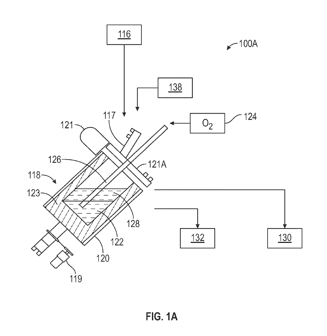
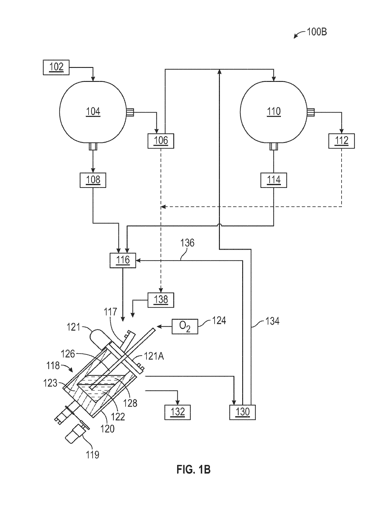
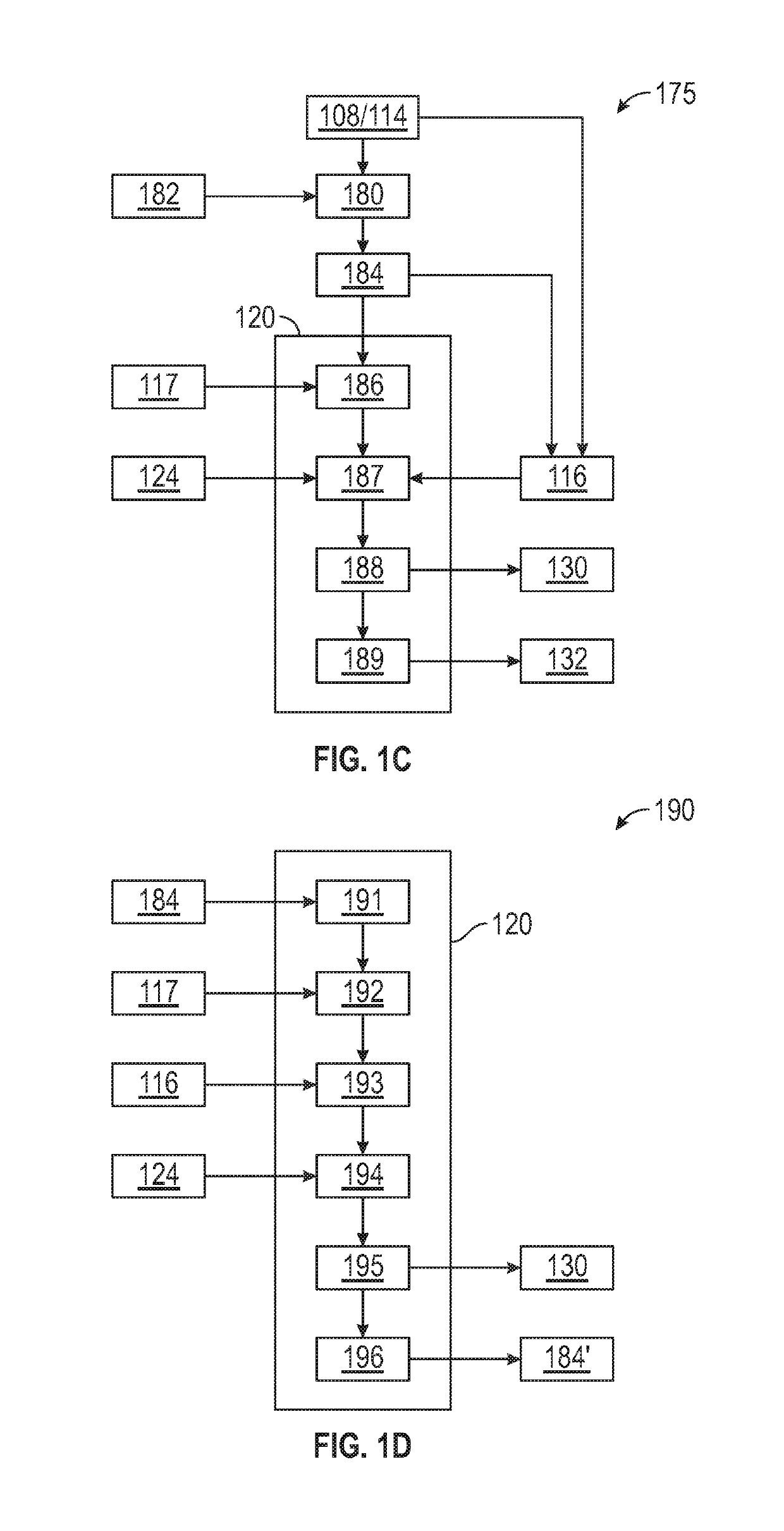
[0198](a) introducing a converter feed into a pot of a converter holding a molten alloy pool (preferably comprising nickel), wherein the converter feed comprises:[0199](i) 100 parts by weight of a collector alloy comprising no less than 0.5 wt % PGM, no less than 40 wt % iron, and no less than 0.5 wt % nickel, (and preferably no more than 3 wt % sulfur and no more than 3 wt % copper), based on the total weight of the collector alloy; and[0200](ii) if an added flux material comprises more than 10 weight percent silica and more than 10 weight percent of calcium oxide, magnesium oxide, or a combination of calcium oxide and magnesium oxide, by weight of the added flux material, less than 20 parts by weight of the added flux material;

[0201](b) injecting oxygen-containing gas into the alloy pool to convert i...

embodiment 1

2. The process of embodiment 1, further comprising:

[0205]lining the pot with a refractory material; and

[0206]supplying a refractory protectant to the pot holding the alloy pool at a rate up to 20 parts by weight refractory protectant per hundred parts by weight of the collector alloy in the converter feed, preferably not more than 18 parts by weight per 100 parts by weight of the collector alloy, and more preferably at a rate between 5 and 15 parts by weight refractory protectant per 100 parts by weight of the collector alloy.

embodiment 2

3. The process of embodiment 2, wherein the refractory protectant is supplied to the pot (i) after initially melting the alloy pool and prior to commencing step (b), (ii) during one or both of steps (a) and (b), and / or (iii) after stopping one or both of steps (a) and (b) to tap the low-density layer in step (d), prior to resuming said one or both of steps (a) and (b).

4. The process of embodiment 2 or embodiment 3, wherein the refractory protectant is supplied to the pot together with the collector alloy introduced in step (a).

5. The process of embodiment 2 or embodiment 3, wherein the refractory protectant is supplied to the pot separately from the collector alloy introduced in step (a), preferably wherein the supply of refractory protectant to the pot is periodic.

6. The process of any of embodiments 2 to 5, wherein the refractory protectant comprises a component in common with the refractory material, preferably wherein the component in common comprises alumina.

7. The process of a...


PUM


Abstract

Converting process with partial pre-oxidation of PGM collector alloy. The process includes partially pre-oxidizing a raw alloy, introducing an initial charge of the partially pre-oxidized alloy into a converter pot, melting the initial charge, introducing converter feed to the pool, oxygen injection into the pool, tapping the slag, and tapping the PGM-enriched alloy. The collector alloy contains no less than 0.5 wt % PGM, 40 wt % iron, and 0.5 wt % nickel, and no more than 3 wt % sulfur and 3 wt % copper. The process can also include low- or no-flux converting; using a refractory protectant in the converter; magnetic separation of slag; recycling part of the slag to the converter; smelting catalyst material in a primary furnace to produce the collector alloy; and / or smelting the converter slag in a secondary furnace with slag from the primary furnace.

Description

CROSS-REFERENCE TO RELATED APPLICATION[0001]This application is a continuation-in-part of our earlier co-pending application U.S. Ser. No. 16 / 397,441, filed Apr. 29, 2019, now U.S. Pat. No. ______.BACKGROUND OF THE INVENTION[0002]The platinum group metals, i.e., ruthenium, rhodium, palladium, osmium, iridium, and platinum (“PGM”), are often recovered from used catalyst materials such as, for example, automotive catalytic converters. The catalyst materials are smelted in a furnace, typically with a flux material such as CaO, and the PGM are preferentially collected in an alloy pool below the slag. While the PGM are dilute in the furnace slag, nevertheless these losses can be significant due to the high volume of slag and a general inability to economically recover the dilute values. The PGM collector alloys may contain up to 12 wt % PGM, and usually contain more than 40 wt % iron. Enrichment is necessary if a higher PGM content is desired.[0003]PGM enrichment of iron-rich, sulfide-le...

Claims


Application Information

Patent Timeline
Patent Type & Authority Applications(United States)
IPC IPC(8): C22C33/04C22C38/00C22C38/42C22C38/02C22C38/50
CPCC22C33/04C22C38/002C22C38/50C22C38/02C22C38/42C22B11/026C22C1/02C22B11/02C22B11/025C22C38/34C22C38/60C22C19/05C21B3/04Y02W30/50Y02P10/20C22B9/10C22B9/16C22B7/04C22B9/05C22B1/005C21C5/36C21C5/44C21C5/4606C21C5/466C22B11/048C22B7/009C22B9/106
Inventor ALBRECHT, EDWARD W.MCCULLOUGH, STEVEN D.
Owner TECHEMET LP
Why Eureka
Try Eureka