Liquid ejection head

a liquid ejection and ejection head technology, applied in printing and other directions, can solve the problems of increasing the heat generation amount affecting reliability, and failure of the connection (bonding) between the inner leads and the wiring lines of the electric wiring substrate under the same conditions to achieve stable bonding and shorten the bonding time

Active Publication Date: 2016-06-28
CANON KK
View PDF4 Cites 3 Cited by
  • Summary
  • Abstract
  • Description
  • Claims
  • Application Information

AI Technical Summary

Benefits of technology

[0011]Therefore, the present invention provides a liquid ejection head that makes it possible to achieve both of the stability of bonding and the shortening of a bonding time when bonding an electric wiring substrate where thick leads applied with large current and thin leads applied with small current are mixed and a printing element substrate.
[0013]The liquid ejection head of the present invention makes it possible to achieve both of the stability of bonding between an electric wiring substrate where thick leads applied with large current and thin leads applied with small current are mixed and a printing element substrate, and the shortening of a bonding time.

Problems solved by technology

As described, in the situation where the current flowing through the liquid ejection head is increased, increasing a current amount without changing a line width of an electric wiring substrate may increase a heat generation amount of the electric wiring substrate to impair reliability.
As described, in the case where line width is different between the leads for logic and the leads for energy generating element driving current, the connection (bonding) between the inner leads and wiring lines of an electric wiring substrate under the same conditions fails in stable bonding.

Method used


Image

  • Liquid ejection head
  • Liquid ejection head
  • Liquid ejection head

Examples


first embodiment

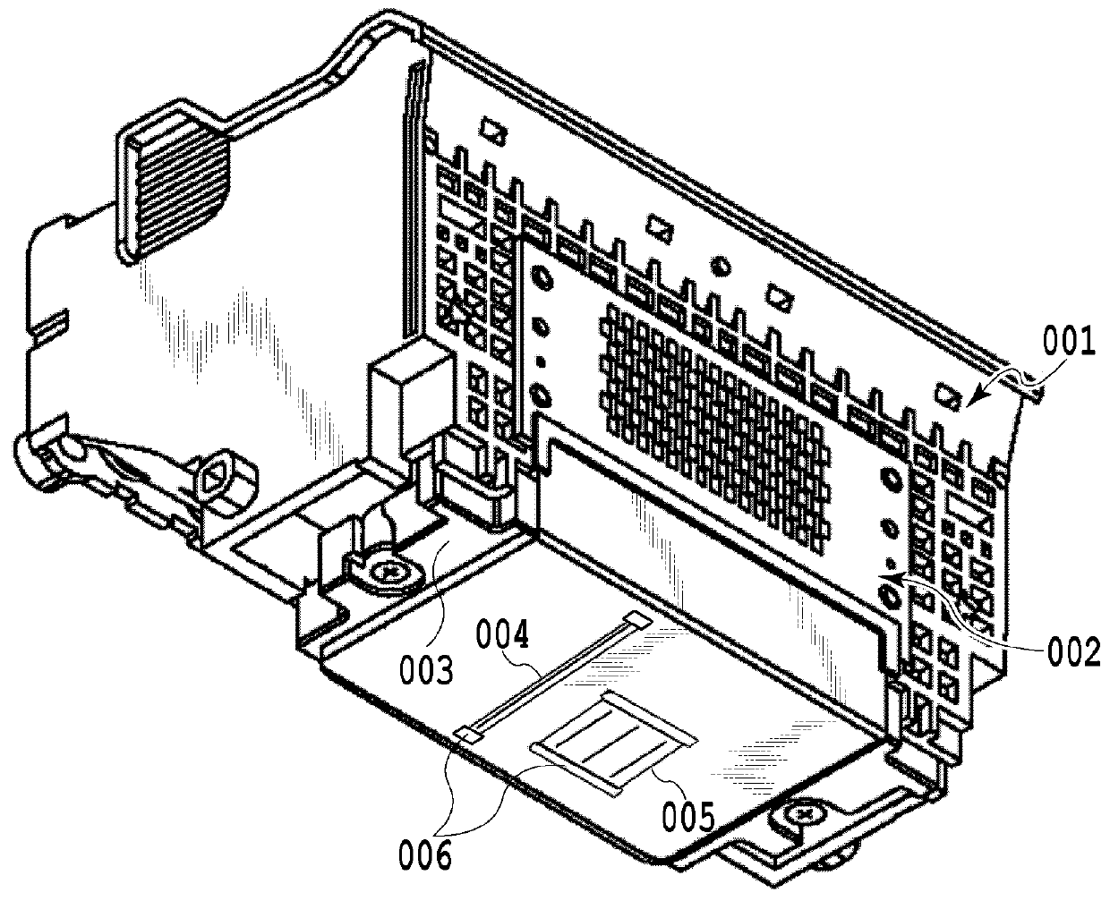
[0024]FIG. 1 is a perspective view illustrating a liquid ejection head of the present invention. The liquid ejection head 001 includes printing element substrates A and B 004 and 005 for ejecting liquid. Each of the printing element substrates A and B 004 and 005 includes multiple fine ejection ports for ejecting ink and unillustrated energy generating elements corresponding to the ejection ports.

[0025]From the printing element substrate A 004, black ink for printing a monochrome image is ejected. From the printing element substrate B 005, cyan ink, magenta ink, and yellow ink for printing a color image are ejected. The printing element substrates are connected to an electric wiring substrate 003. The connecting parts between the printing element substrates and the electric wiring substrates 003 are sealed by sealant 006.

[0026]The electric wiring substrate 003 is bent at an end part of a surface on which the printing element substrates are mounted, and connected to an electric wirin...

second embodiment

[0043]A second embodiment of the present invention is described below with reference to drawings. Note that a basic configuration of the present embodiment is the same as that of the first embodiment, and therefore only a characteristic configuration is described below.

[0044]In the present embodiment, a configuration in which a wiring layer of a printing element substrate is a single layer is described below.

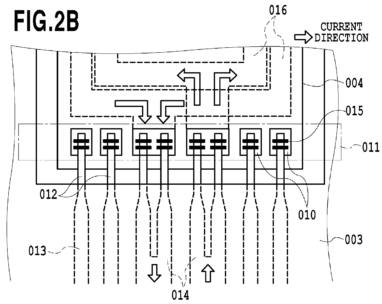
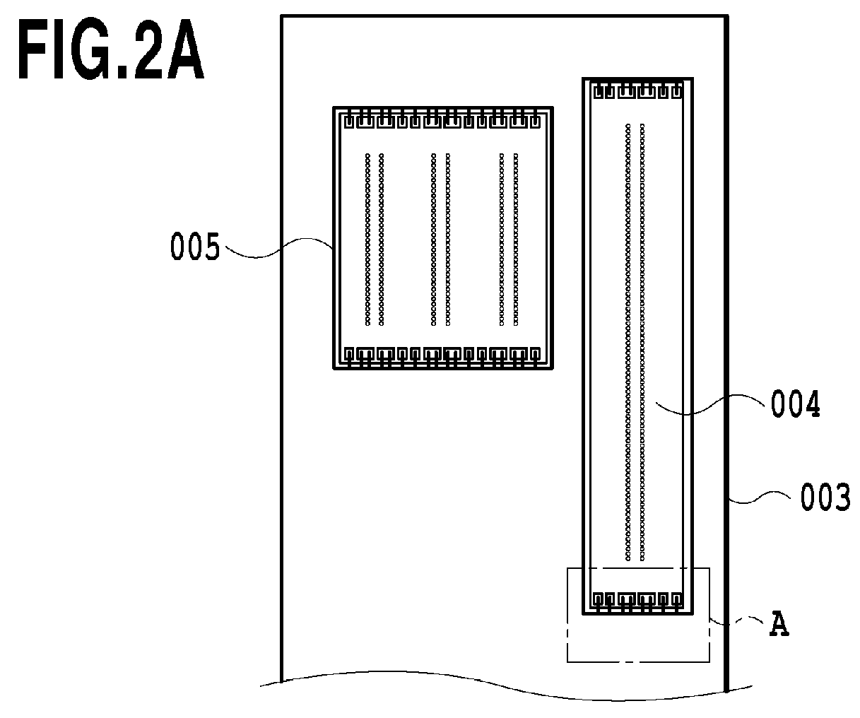
[0045]FIGS. 3A and 3B are views illustrating printing element substrates connected to an electric wiring substrate in the present embodiment. As in FIGS. 2A and 2B, to facilitate easy understanding of the connecting state, the illustration is given with sealant removed. In the printing element substrate A 204 in FIG. 3A, the wiring layer for current flowing through the printing element substrate is configured as a single layer. For this reason, only the central wiring line 216 that is a wiring line for driving energy generating elements is connected with a wiring line 014 of a s...

third embodiment

[0047]A third embodiment of the present invention is described below with reference to drawings. Note that a basic configuration of the present embodiment is the same as that of the first embodiment, and therefore only a characteristic configuration is described below.

[0048]The present embodiment is optimally configured for the case where the number of wiring layers is one, and the number of connecting terminals is multiple.

[0049]FIGS. 4A and 4B are views illustrating printing element substrates connected to an electric wiring substrate in the present embodiment. As in FIGS. 2A and 2B, to facilitate easy understanding of the connecting state, the illustration is given with sealant removed. The printing element substrate A 304 illustrated in FIG. 4A is 1 inch long, and includes 1280 ejection ports on both sides at a resolution of 1200 dpi in a staggered manner across an unillustrated common ink supply port, i.e., 640 ejection ports on one side at a resolution of 600 dpi.

[0050]The pri...


PUM


Abstract

Provided is a liquid ejection head that makes it possible to achieve both of the stability of bonding and the shortening of a bonding time when bonding an electrical wiring substrate where thick leads applied with large current and thin leads applied with small current are mixed and a printing element substrate. For this purpose, the electrical wiring substrate includes wiring lines having different widths, and each of the wiring lines of the electric wiring substrate and a connecting terminal of the printing element substrate are connected by inner leads whose number corresponds to width of the wiring line.

Description

BACKGROUND OF THE INVENTION[0001]1. Field of the Invention[0002]The present invention relates to a liquid ejection head mounted in a liquid ejection apparatus adapted to eject liquid.[0003]2. Description of the Related Art[0004]At present, on a printing element substrate mounted in a liquid ejection head, multiple connecting terminals for connecting to an electric wiring substrate of the liquid ejection head are provided. The connecting terminals provided on the printing element substrate have connecting members made of Au, and the electric wiring substrate has inner leads for corresponding connecting terminals, respectively. The wiring substrate and the printing element substrate are connected to each other through the connecting members and the inner leads. The electric wiring substrate has outer leads on the side opposite to the inner leads, which are connected to an electric wiring member including connecting terminals for connecting to a liquid ejection apparatus.[0005]To conne...

Claims


Application Information

Patent Timeline
Patent Type & Authority Patents(United States)
IPC IPC(8): B41J2/14B41J2/05B41J2/175
CPCB41J2/14072B41J2/1753B41J2002/14491
Inventor AKAMA, YUICHIROKUDO, KIYOMITSUKIMURA, SATOSHITAKAGI, YOSUKE
Owner CANON KK
Why Eureka
Try Eureka