Durable flexible circuit board for transparent display board and assembling method thereof

a flexible circuit board and display board technology, applied in the direction of dielectric characteristics, circuit optical details, instruments, etc., can solve the problems of short lifetime, high consumption of electricity, and risk of electric shock accident or fire, etc., to improve the durability of flexible circuit boards, increase the bonding area, and the effect of ultrasonic bonding

Active Publication Date: 2018-05-24
G SMATT
View PDF0 Cites 3 Cited by
  • Summary
  • Abstract
  • Description
  • Claims
  • Application Information

AI Technical Summary

Benefits of technology

[0034]Another object of the present invention is to provide a durable flexible circuit board for a transparent display board, the durable flexible circuit board being capable of reducing a temperature difference and a pressure difference between outermost connection terminals and inside connection terminals during ultrasonic bonding, thereby enabling stable power line connection and signal line connection, shortening a bonding time, and increasing a bonding force which results in improved durability thereof.
[0036]As described above, the present invention improves the durability of a flexible circuit board by increasing a bonding area between a hard substrate and a flexible film. In addition, the present invention enables ultrasonic bonding of a flexible circuit board by providing a hard portion to the flexible circuit board, thereby increasing production productivity of the flexible circuit board.
[0037]In addition, according to the present invention, since power lines and signal lines are integrated in a single flexible circuit board, it is not necessary to form additional metal terminals on a transparent plate. For this reason, resistance is uniformized over an overall area of the flexible circuit board, resulting in uniform brightness of a transparent display board. Furthermore, since the power lines and the signal lines can be simultaneously connected, production productivity can be improved.

Problems solved by technology

Neon lamps and cold cathode lamps (CCL) consume much electricity, have a risk of causing an electric shock accident or fire, and have a short lifetime because they operate at high voltages.
In addition, EEFLs and CCFLs are not suitable for outdoor use because they operate on high frequency voltages and have problems of a low illumination and a short lifetime.
However, the above-described light emitting devices have a limitation in the design improvement because of constrains of lamp sizes and presence of accessories such as a stand that is used to support the light emitting devices.
For this reason, in the case of the transparent display board, since the power line patterns and the signal line patterns (flexible circuit board 40) are connected through separate connection processes, an assembling method thereof is complicated.
For this reason, there is a problem that brightness varies according to positions of the metal power connection terminals 30 and 30′.
Therefore, unnecessary standby energy consumption is required, and an ambient air temperature rises due to continuous heat generation, thereby deteriorating working conditions.
That is, there is a problem that the manufacturing time is long.
However, even though uniform pressure is applied to the signal connection terminals of the conventional flexible circuit board during the ultrasonic vibration, the pressure over an overall area of the flexible circuit board is not uniform due to the structural characteristics.
Therefore, the pressure applied thereto is not uniformly distributed.
However, the vibration is not well transferred to positions where the pressure is low and thus the temperature does not easily rise there.
In conclusion, the conventional ultrasonic bonding method for the conventional flexible circuit board has problems of low bonding force and a risk of electric disconnection due to presence of locally uncured portions attributable to non-uniformity in temperature and pressure between the inside portion and the periphery portion of the flexible circuit board.

Method used


Image

  • Durable flexible circuit board for transparent display board and assembling method thereof
  • Durable flexible circuit board for transparent display board and assembling method thereof
  • Durable flexible circuit board for transparent display board and assembling method thereof

Examples


Embodiment Construction

[0048]Hereinafter, exemplary embodiments of a transparent display board with a signal transfer device integrated with a power line will be described with reference to the accompanying drawings.

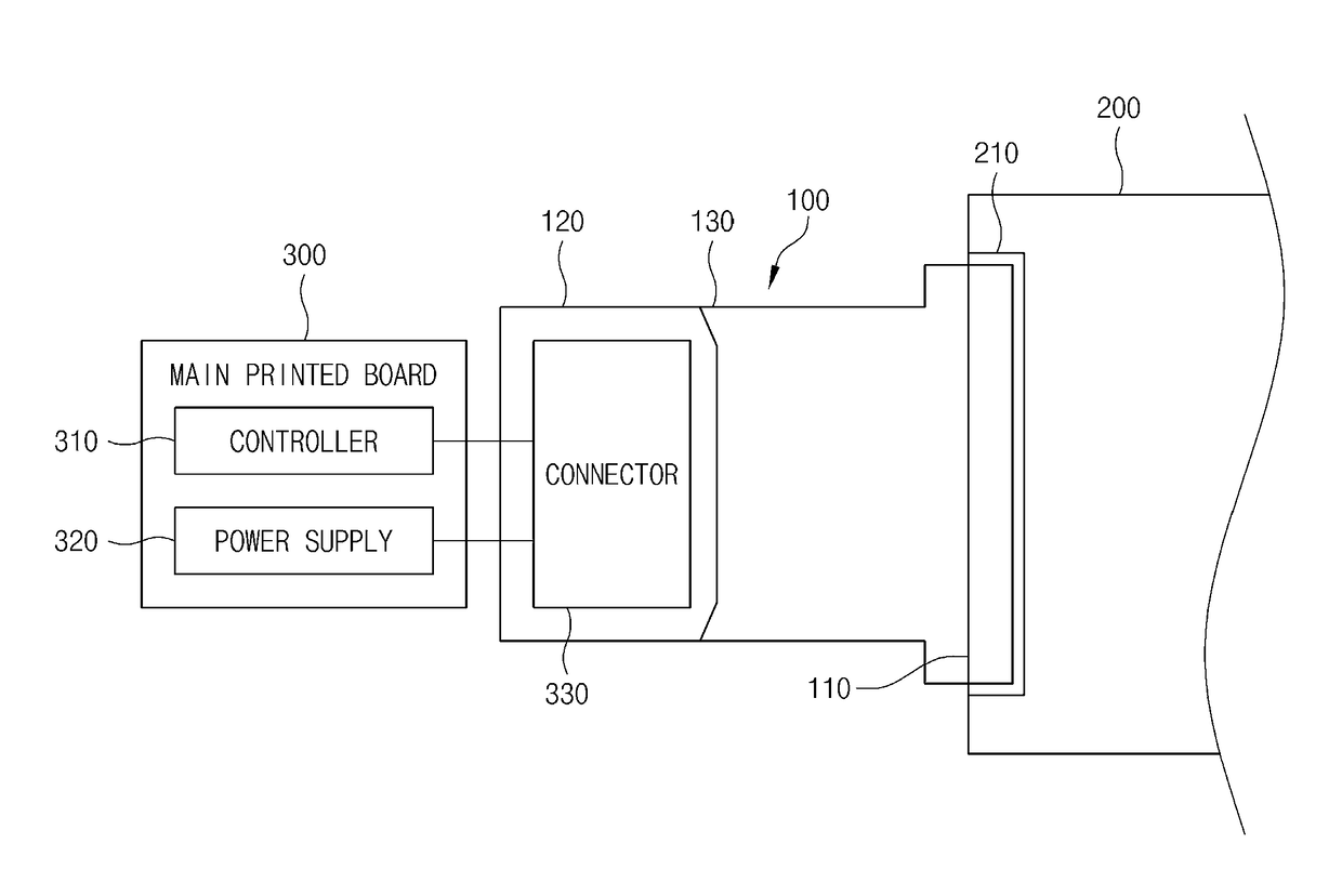
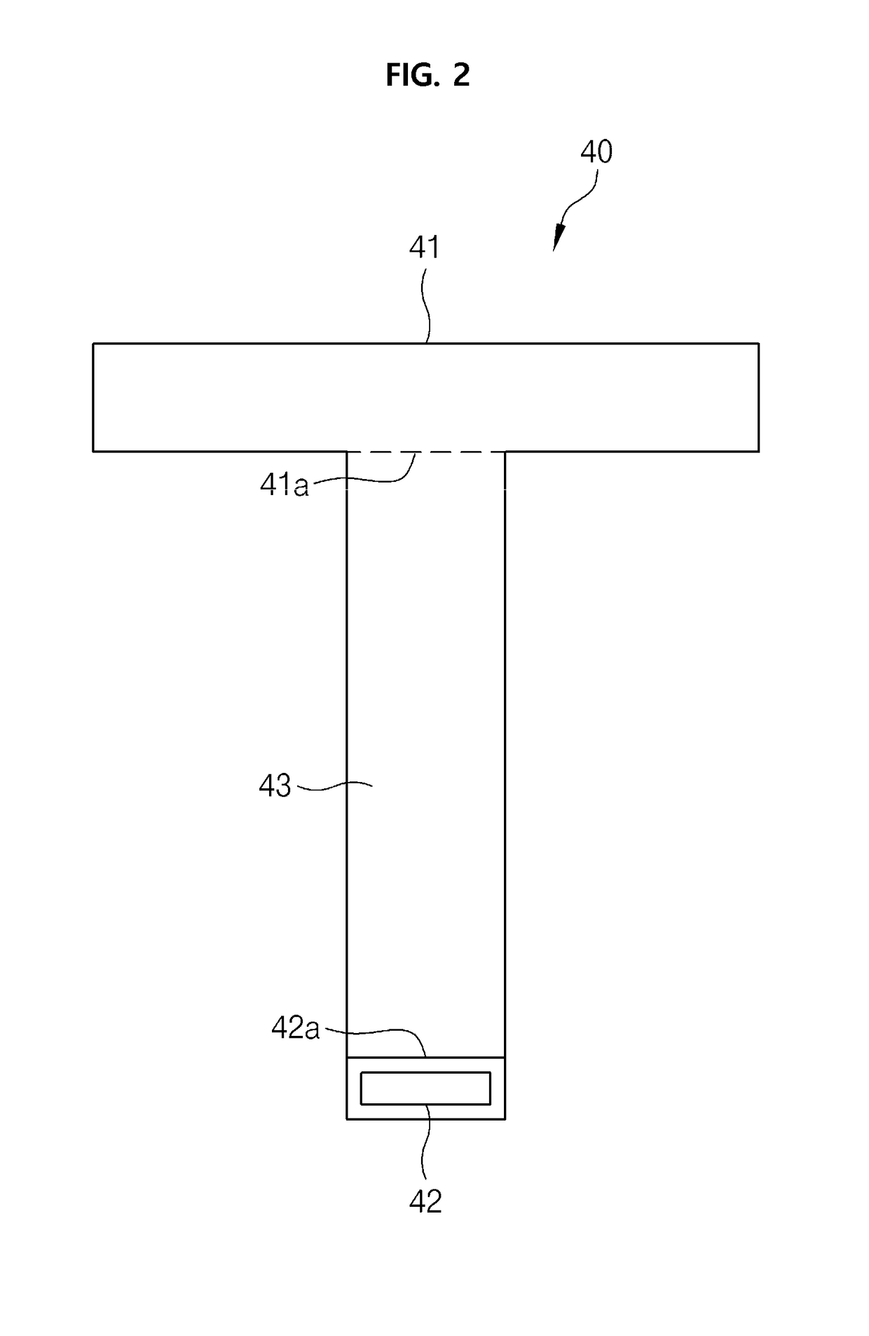
[0049]FIG. 3 is a schematic view illustrating a transparent display board to which a durable flexible circuit board according to one embodiment of the invention is applied and FIG. 4 is a schematic plan view illustrating the flexible circuit board according to the embodiment of the invention.

[0050]With reference to FIGS. 3 and 4, the durable flexible circuit board for a transparent display board, according to the embodiment of the invention, includes a driver board 300, a transparent plate 200 on which a plurality of light emitting elements is provided, and a flexible circuit board 100 connected between the driver board 300 and the transparent plate 200.

[0051]One surface of the driver board 300 is provided with a controller 310 and a power supply 320. The controller 310 generates control signa...


PUM


Abstract

A durable flexible circuit board for a transparent display board is connected between a driver board provided with at least one of a power supply and a controller and a transparent plate provided with a plurality of light emitting elements. The flexible circuit board includes an electrode bonding portion provided with a plurality of signal connection terminals for transferring control signals, at least one power connection terminal for transferring electric power, and at least one dummy terminal disposed outside the signal connection terminal or the power connection terminal disposed at the outermost side. The dummy terminal resists vibration and pressure applied to the signal connection terminal or the power connection terminal disposed at the outermost side. The signal connection terminal and the power connection terminal are integrated in the flexible circuit board.

Description

CROSS REFERENCE TO RELATED APPLICATION[0001]The present application claims priority to Korean Patent Application No. 10-2016-0156453, filed Nov. 23, 2016, the entire contents of which is incorporated herein for all purposes by this reference.BACKGROUND1. Field of the Invention[0002]The present invention relates to a durable flexible circuit board for a transparent display board and an assembling method thereof.2. Description of the Related Art[0003]As outdoor sign boards, electronic display boards using neon lamps, cold cathode lamps (CCL), or light emitting diodes (LED) are broadly used. Meanwhile, as indoor light emitting devices, external electrode fluorescent lamps (EEFL) or cold cathode fluorescent lamps (CCFL) are used.[0004]Neon lamps and cold cathode lamps (CCL) consume much electricity, have a risk of causing an electric shock accident or fire, and have a short lifetime because they operate at high voltages. In addition, EEFLs and CCFLs are not suitable for outdoor use beca...

Claims


Application Information

Patent Timeline
Patent Type & Authority Applications(United States)
IPC IPC(8): H05K1/03H05K1/09H05K1/14H05K3/32
CPCH05K1/0393H05K1/09H05K1/147H05K2201/10106H05K2201/09409H05K2203/0285H05K3/32H05K1/118H05K3/365H05K2201/09372H05K2201/09781H05K1/0274H05K3/323H05K3/361H05K3/4691H05K2201/0108H05K2201/09145H05K2201/10128H05K2201/2009G09F13/08H05K1/111H05K3/281
Inventor KIM, SUNG SOOLEE, YOUNG WOOLEE, HO JOON
Owner G SMATT
Why Eureka
Try Eureka