
Door sill assembly with sealed zone for exterior doors

a door sill and sealing technology, applied in the field of exterior doors, can solve the problems of inconvenient configuration, inconvenient use, and inconvenient installation of door sills,

Active Publication Date: 2016-07-12
FORIMPEX
View PDF21 Cites 10 Cited by
  • Summary
  • Abstract
  • Description
  • Claims
  • Application Information

AI Technical Summary

Benefits of technology

Effectively prevents water infiltration by forming a pressure-equalized drainage zone and a sealed zone, ensuring compliance with water penetration resistance standards and maintaining a watertight seal without relying on weep holes or high water retention configurations.

Problems solved by technology

In exterior door assembly designs, the threat of water penetration is the greatest at the bottom of the door.
According to some new regulatory standards, the water penetration resistance test will be a primary source of concern because a minute water penetration on the interior of the door could result in a door sill assembly not meeting the standards.
There are other threshold designs, such as a “water retention sill”, that feature a water retention structure at the sill portion, and a relatively high threshold, but such a configuration may not be suitable for using as an entrance door.

Method used


Image

  • Door sill assembly with sealed zone for exterior doors
  • Door sill assembly with sealed zone for exterior doors
  • Door sill assembly with sealed zone for exterior doors

Examples


Embodiment Construction

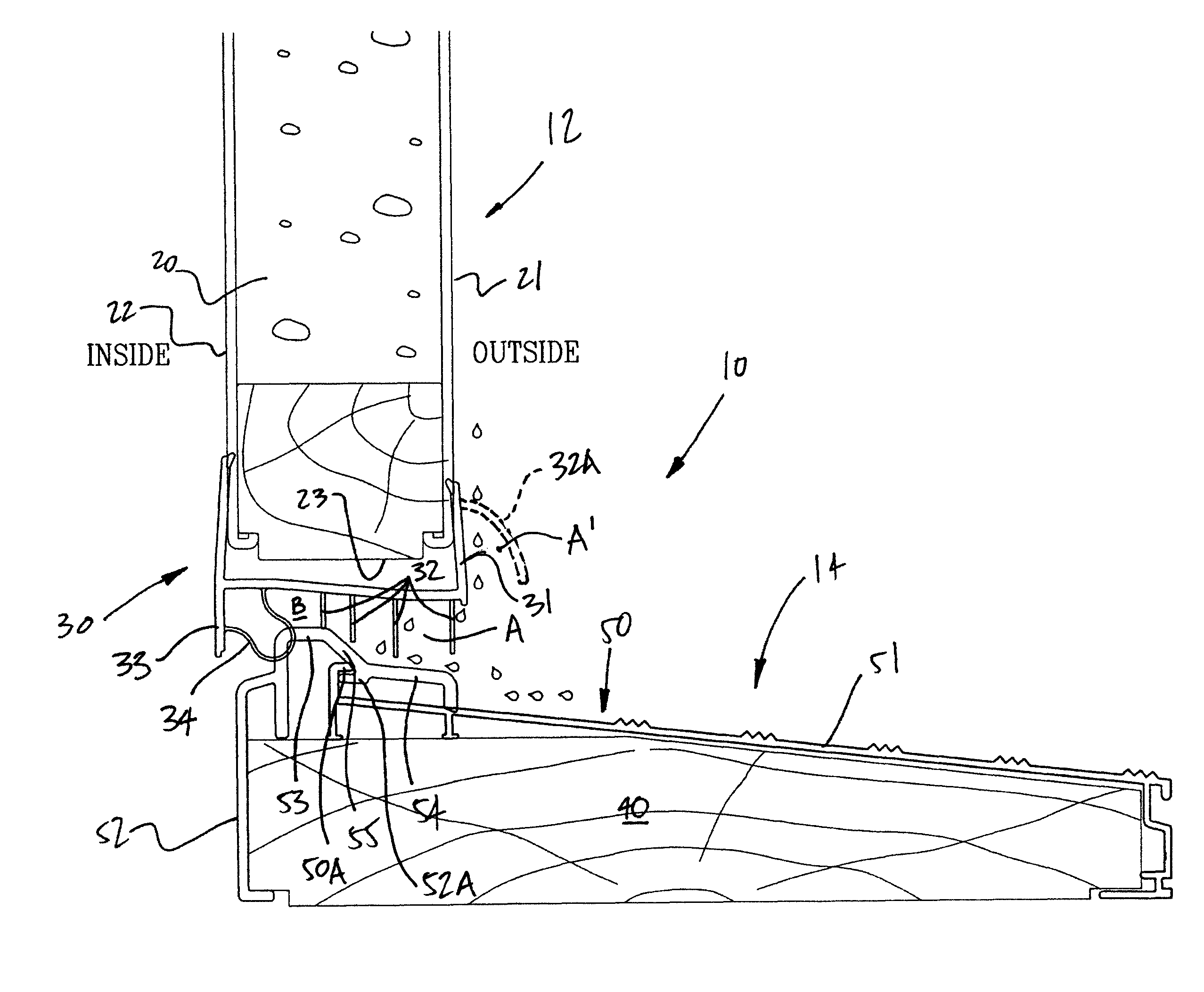
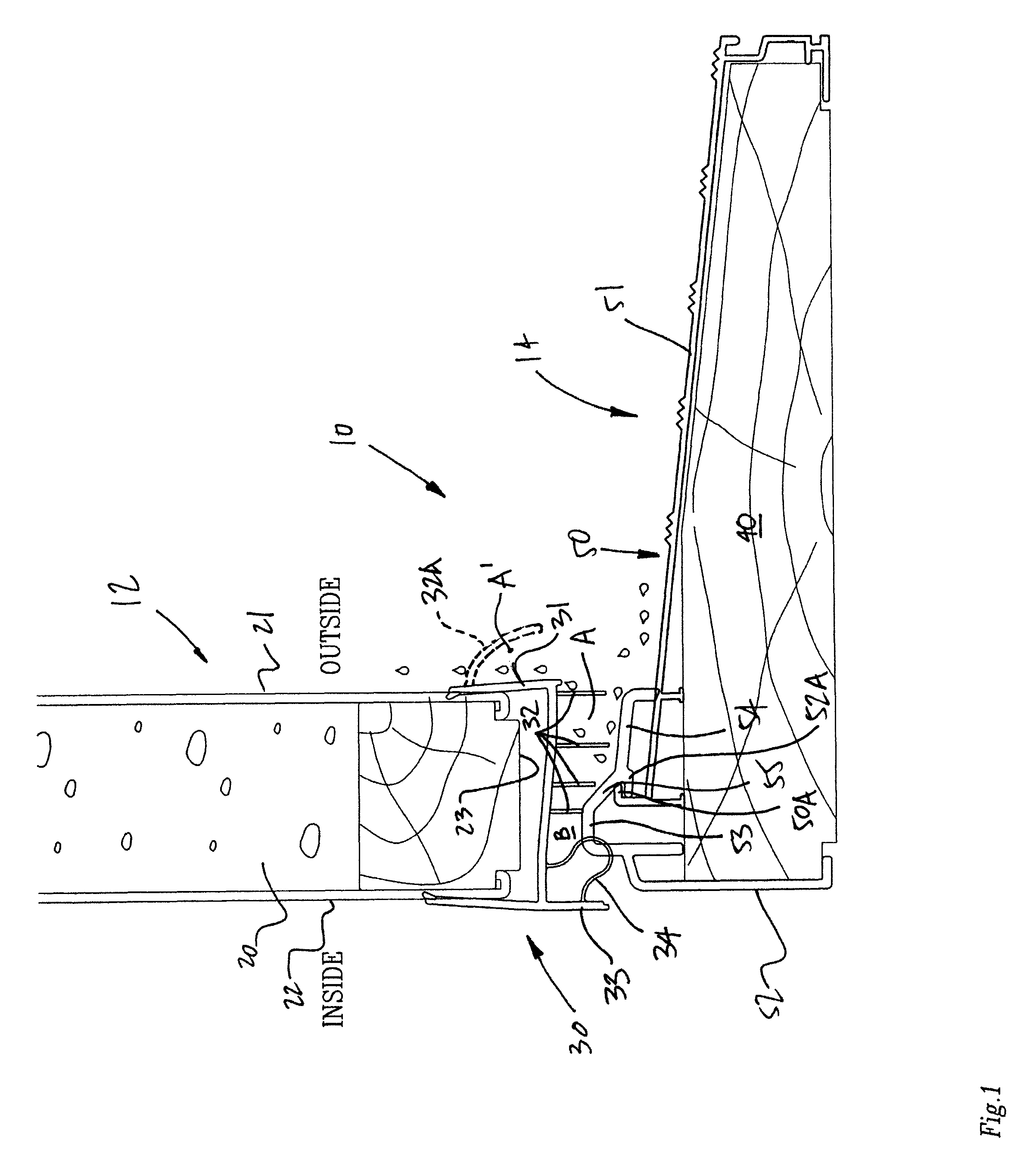
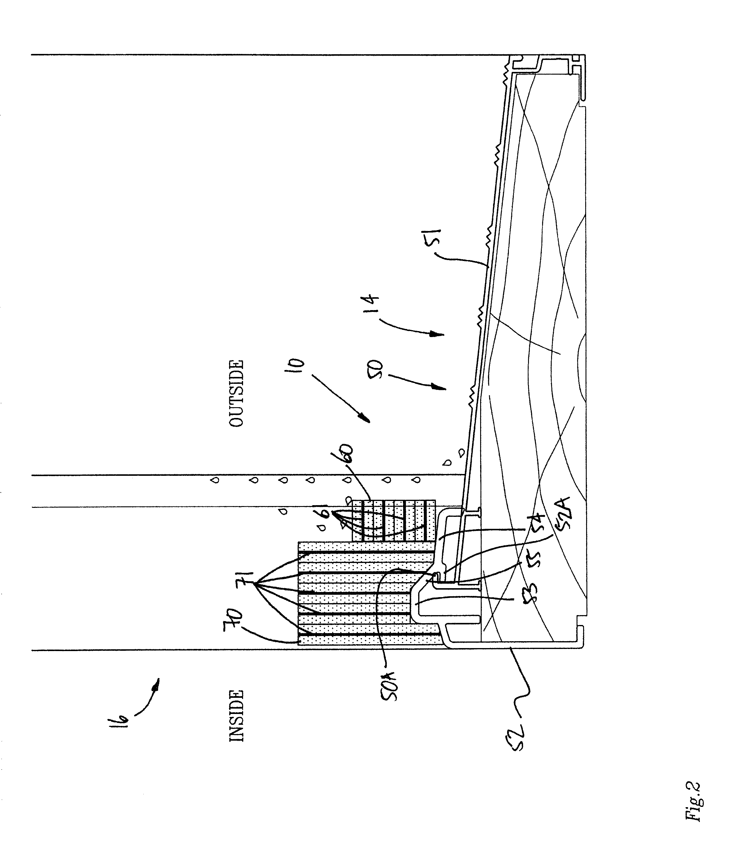
[0010]Referring to the drawings and more specifically to FIG. 1, there is illustrated at 10 a door sill assembly in accordance with an embodiment of the present disclosure. The door sill assembly 10 is between a door 12 and a sill 14, and may have components in the jambs 16 (FIG. 2). The door 12 is of to type that is pivotally mounted to the doorframe so as to be pivoted between an open position, and a closed position as in FIG. 1. Such a door may be known as a hinged door, a leaf door, an entrance door, etc. Therefore, as illustrated in the figures, the door 12 may be between the inside and the outside of a building. Moreover, the door 12 typically pivots toward the interior to reach the open position, although the door 12 could pivot toward the exterior as well. Moreover, the door 12 could be fixed or sidelite.

[0011]The door 12 comprises a door slab 20 that is made of any appropriate material or combinations thereof such as wood, metals (e.g., steel), foam core, glass, etc. In FIG...


PUM

PropertyMeasurementUnit
thresholdaaaaaaaaaa
pressureaaaaaaaaaa
sill thresholdaaaaaaaaaa

Abstract

A door sill assembly comprises a sill threshold defining an upper step portion and a lower step portion. A sweep is connected to a bottom of a door slab of a door, the sweep comprising deflectors projecting downwardly from the door slab. An outermost deflector is vertically aligned with and spaced apart from the lower step portion when the door is closed to form a pressure-equalized zone open to the exterior. A second deflector is vertically aligned and in contact with the upper step portion when the door is closed. A seal is positioned interiorly relative to the deflectors and is vertically aligned with the upper step portion to form a sealed zone with the second one of the deflectors and the upper portion when the door is closed.

Description

CROSS-REFERENCE TO RELATED APPLICATIONS[0001]The present application claims priority on Canadian Patent No. 2,775,167 filed Apr. 20, 2012, the entire contents of which is incorporated herein by reference.FIELD OF THE APPLICATION[0002]The present application relates to exterior doors such as doors providing access to the interior of a building from the outside, and more specifically to door sill assemblies for such exterior doors.BACKGROUND OF THE ART[0003]In exterior door assembly designs, the threat of water penetration is the greatest at the bottom of the door. Accordingly, to increase watertightness, the design of the sill threshold is crucial. Commonly used threshold designs, such as a flat sill, a fixed or adjustable threshold on an inclined sill approach, or a “dam” type threshold equipped with weep holes with an adjustable sweep, all manage water drainage, but may still allow some water infiltration. According to some new regulatory standards, the water penetration resistance...

Claims


Application Information

Patent Timeline
Patent Type & Authority Patents(United States)
IPC IPC(8): E06B1/70E06B7/26E06B7/23E06B7/28E06B1/52
CPCE06B1/70E06B1/52E06B7/2312E06B7/2316E06B7/26E06B7/28
Inventor GILBERT, CLAUDEBILODEAU, ANDREKOBAYASHI, TETSUYA
Owner FORIMPEX
Learn More