Asymmetric muzzle compensator for firearm

a compensator and asymmetric technology, applied in the direction of muzzle attachment, etc., can solve the problems of counteracting part of the recoil force, reducing or neutralizing the effect of the muzzle blast,

Active Publication Date: 2016-08-16
SPIKES TACTICAL
View PDF14 Cites 8 Cited by
  • Summary
  • Abstract
  • Description
  • Claims
  • Application Information

AI Technical Summary

Problems solved by technology

First, a muzzle brake may present a surface against which the propellant gases impact, causing that transferred force to pull the barrel forward, counteracting part of the recoil forces.
Second, redirection of propellant gases laterally, or even somewhat rearwardly, reduce or neutralize the effect of the muzzle blast.

Method used


Image

  • Asymmetric muzzle compensator for firearm
  • Asymmetric muzzle compensator for firearm
  • Asymmetric muzzle compensator for firearm

Examples


Embodiment Construction

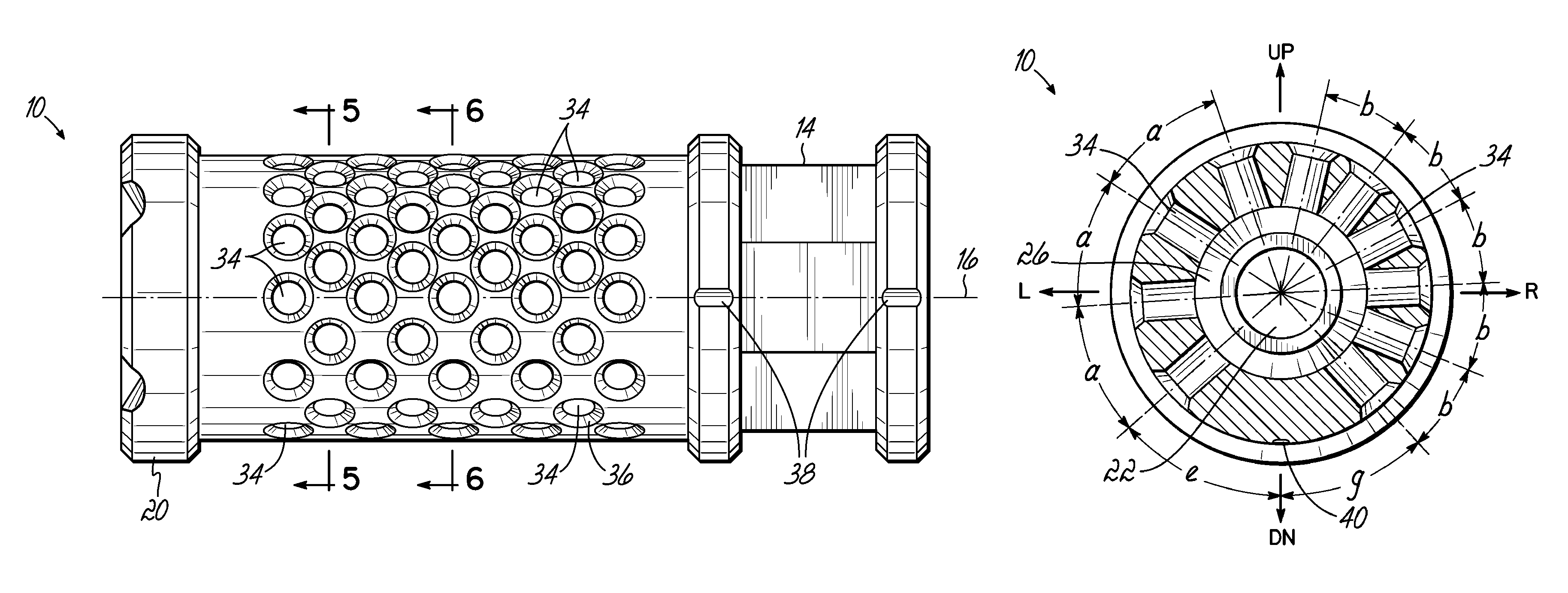
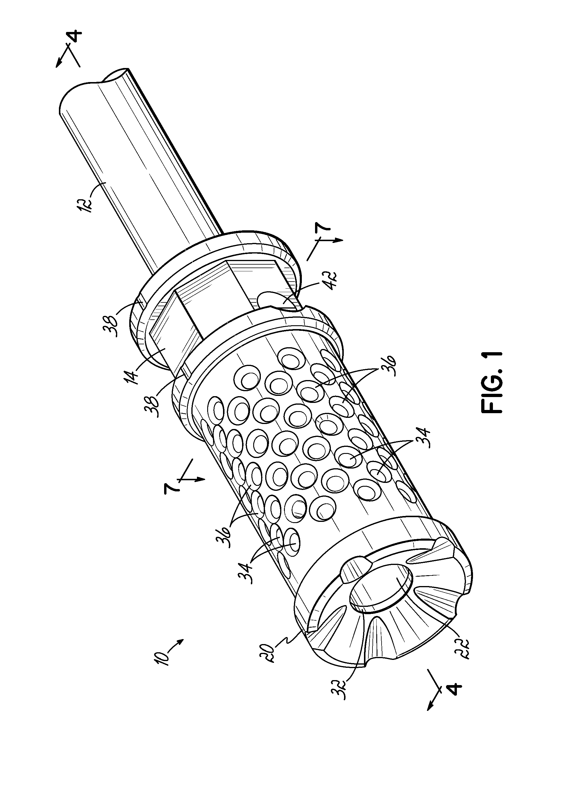
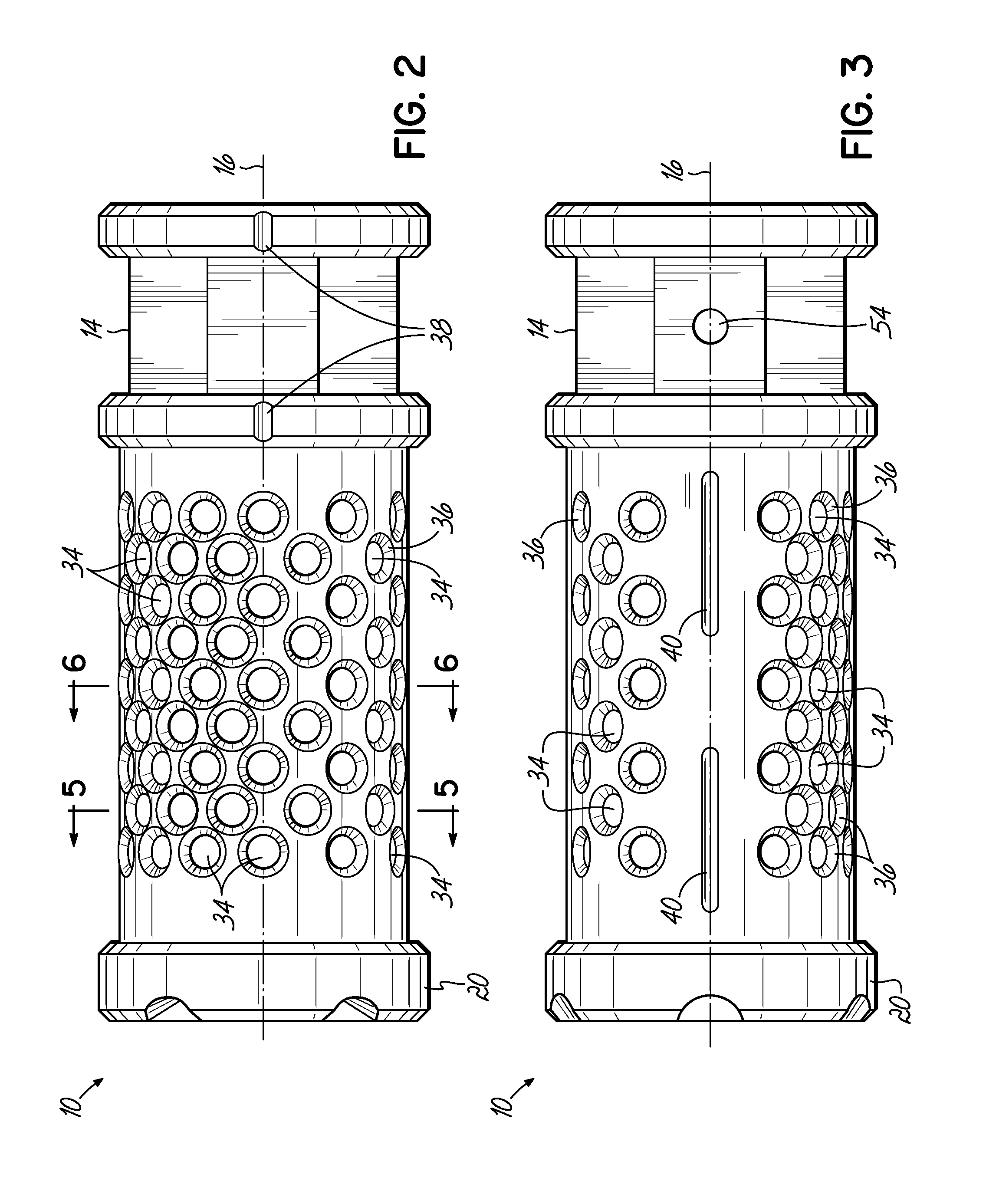
[0023]Referring now to the various figures of the drawing, and first to FIGS. 1-3, therein is shown at 10 a compensator according to one embodiment of the present invention. The illustrated device 10 is in the form of an attachment that may be removably coupled to the muzzle end of a firearm barrel 12, by threadedly engaging mounting threads 44 provided on a radially inner surface of the device 10 with threads 46 provided on a radially outer surface of the muzzle end of the barrel 12. The body of the device 10 may include one or more wrench flats 14 to facilitate attachment of the device 10 to the barrel 12. The body includes a central passageway having a central axis 16 that is aligned with the axis of the bore 18 of the barrel 12. At a forward end 20 of the device 10, the central passageway opens to an outlet opening 22, which is sized to allow free passage of a projectile therethrough. In practice, the outlet opening 22 must be slightly greater in diameter than the bore 18 of the...


PUM


Abstract

Disclosed is a muzzle device for use with a muzzle end of a firearm barrel. The muzzle device includes a body having a central passageway extending along a central axis and being mountable to the muzzle end of the firearm barrel. A plurality of circumferentially spaced ports are provided on the body and extend generally radially outward from the central axis and open to the central passageway to provide fluid communication between the central passageway and an ambient environment external of the body. The ports are configured to direct propulsion gases generally radially outward therethrough when the firearm is discharged. The body includes a right-side portion and a left-side portion defined by a vertically-oriented imaginary plane, the ports being provided on the body such that the right-side portion directs a greater volume of propulsion gases therethrough than the left-side portion when the firearm is discharged.

Description

FIELD OF INVENTION[0001]This invention relates to devices installed on or integrated into the muzzle of a firearm. More specifically, the invention relates to a compensator intended to counteract the tendency of a firearm's barrel to rise after firing.BACKGROUND OF THE INVENTION[0002]The front end of a firearm (or the muzzle end of the barrel) tends to rise after firing. This occurs primarily because, for most firearms, the center line of the barrel is positioned above a center of contact established between the shooter and the firearm's grips or stock. The reactive force, or the recoil force, created when a bullet is fired and propellant gases, or propulsion gases, exit the muzzle, acts directly along the center line of the barrel and toward the rear of the firearm, where the shooter is generally positioned. When this line of force is above the center of contact between the shooter and the firearm, the force creates a “moment,” or a rotational force, about the center of contact bet...

Claims


Application Information

Patent Timeline
Patent Type & Authority Patents(United States)
IPC IPC(8): F41A21/36
CPCF41A21/36
Inventor MILLER, III, THOMAS JAMES
Owner SPIKES TACTICAL
Why Eureka
Try Eureka