Supercharge Your Innovation With Domain-Expert AI Agents!

Electronic camera

a technology of electronic cameras and support plates, applied in the field of electronic video cameras, can solve the problems of inability to adapt the support to the weight shift of the camera, increased construction complexity, and restricted flexibility in the setup of the camera system, and achieves the effect of precise longitudinal positioning and comfortable positioning of the accessory devi

Inactive Publication Date: 2016-08-16
ARNOLD & RICHTER CINE TECH GMBH & CO BETRIEBS KG
View PDF20 Cites 0 Cited by
  • Summary
  • Abstract
  • Description
  • Claims
  • Application Information

AI Technical Summary

Benefits of technology

The solution provides a stable and flexible attachment system for accessories, allowing for precise positioning and weight distribution adjustments, reducing mechanical clearance and increasing the camera's adaptability to different lenses and accessories.

Problems solved by technology

This has the disadvantage that no adaptation of the support to weight shifts of the camera is possible.
The disadvantage of such an adapter plate is an increased construction complexity since a further components has to be taken along and connected to the adapter plate in addition to the camera itself and any accessory devices.
In addition, there is the fact that the camera body of known video camera typically only has one single connection for holding devices in the form of a standardizes thread at a lower side face of the camera body so that only one single adapter plate can be screwed to the camera body.
The flexibility in the setup of the camera system is thereby in particular restricted.

Method used


Image

  • Electronic camera
  • Electronic camera
  • Electronic camera

Examples


Embodiment Construction

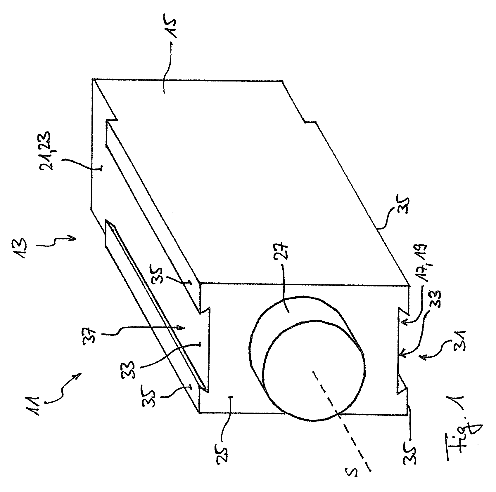
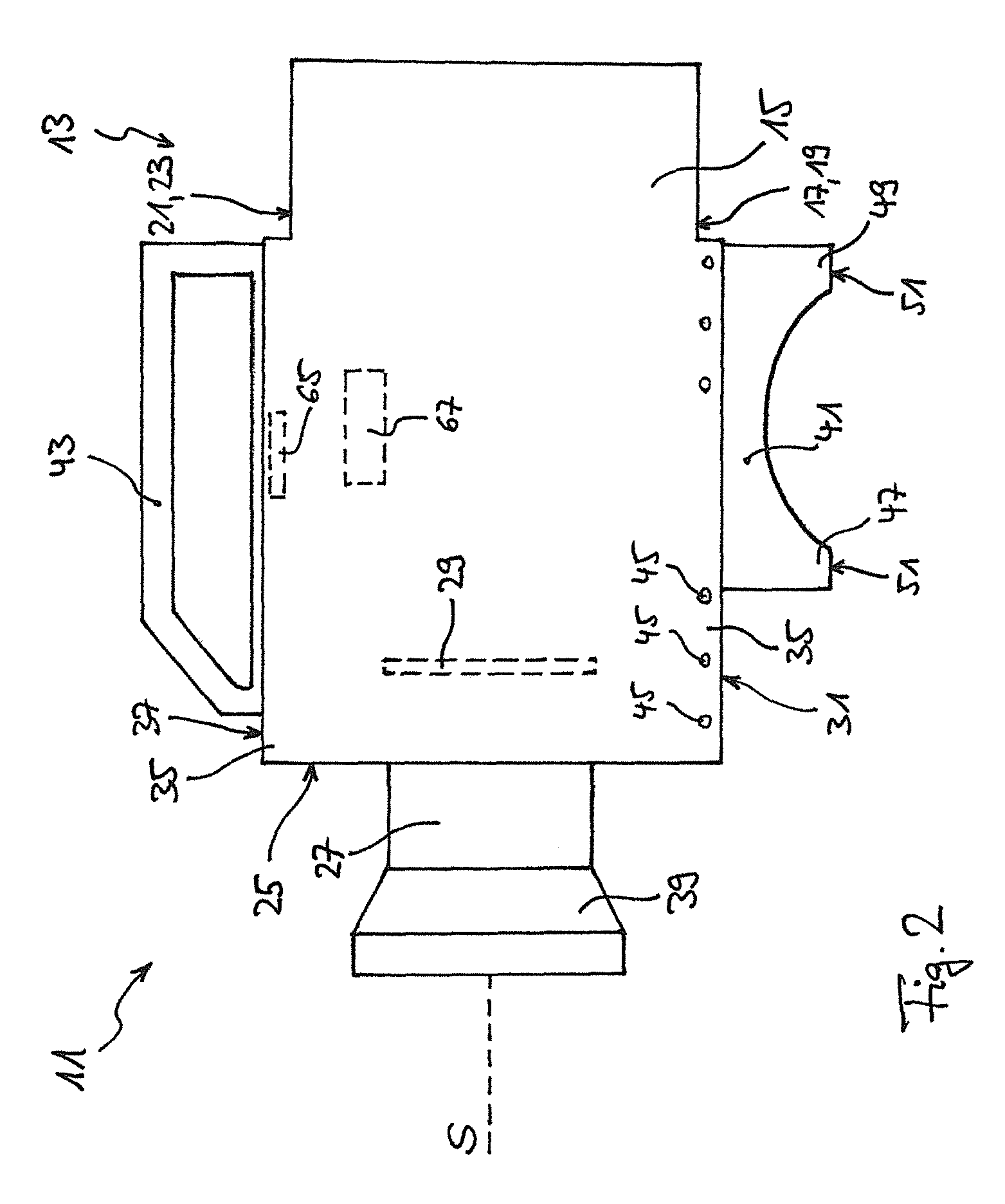
[0057]The embodiment of an electronic video camera 11 shown schematically in FIG. 1 has a camera body 13 which is formed substantially parallelepiped-shaped. The camera body 13 comprises a housing 15 and has a first side face 17 which represents a lower side face of the camera body 13 and is formed as a base pate 19 of the housing 15 and comprises a second side face 21 which represents an upper side face of the camera body 13 opposite to the lower side face and is formed as a top plate 23 of the housing 15. At a front side face 25, the camera body 13 has an objective connection 27 which is here shown in simplified form as a cylinder and which has a substantially circular cross-section.

[0058]A beam path, not shown, runs in the interior of the camera 11 from the objective connection 27 to an image sensor 29 which is arranged within the housing 15 (cf. FIGS. 2 and 3; not shown in FIG. 1). The extension of this beam path outside the camera 11 defines a visual axis S which extends from t...


PUM


Abstract

An electronic video camera comprises a camera body which has an objective connection for interchangeable objectives as well as at least one first side surface and one second side surface, wherein the objective connection defines a visual axis of the video camera. A first longitudinal guide is integrated into the first side face of the camera body and extends in parallel with the visual axis and a second longitudinal guide is integrated into the second side face of the camera body and extends in the same respect in parallel with the visual axis.

Description

CROSS-REFERENCE TO RELATED APPLICATIONS[0001]This application claims priority of German Patent Application DE102013218098.5 filed on Sep. 10, 2013.FIELD OF THE INVENTION[0002]The present invention relates to an electronic video camera (also referred to as an electronic movie camera) comprising a camera body which has an objective connection for interchangeable objectives as well as at least one first side face and one second side face, wherein the objective connection defines a visual axis of the camera (i.e. an axis of vision of the camera).BACKGROUND OF THE INVENTION[0003]The camera bodies of known electronic video cameras are typically parallelepiped-shaped and have at a front side face a usually circular objective connection which defines a visual axis of the camera (central surface normal on the plane of extent of the objective connection) by its alignment. The visual axis thus corresponds to the axis of the light incidence, wherein the light incident through the objective conn...

Claims


Application Information

Patent Timeline
Patent Type & Authority Patents(United States)
IPC IPC(8): H04N5/225G03B17/02
CPCH04N5/2252H04N23/51
Inventor KOPPETZ, MICHAELSPERBER, TIMO
Owner ARNOLD & RICHTER CINE TECH GMBH & CO BETRIEBS KG
Features
  • R&D
  • Intellectual Property
  • Life Sciences
  • Materials
  • Tech Scout
  • Unparalleled Data Quality
  • Higher Quality Content
  • 60% Fewer Hallucinations
Learn More