Light source device having optical members for changing one or more characteristics of excitation light from an excitation light source
a technology of light source and optical member, which is applied in the direction of instruments, lighting and heating apparatus, fibre light guides, etc., can solve the problems of illumination light emitted from such a light source device, and achieve the effect of uniform light distribution characteristics
- Summary
- Abstract
- Description
- Claims
- Application Information
AI Technical Summary
Benefits of technology
Problems solved by technology
Method used
Image
Examples
first embodiment
[0025][First Embodiment]
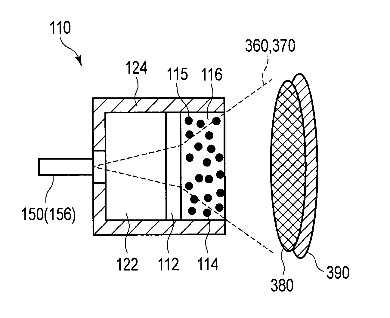
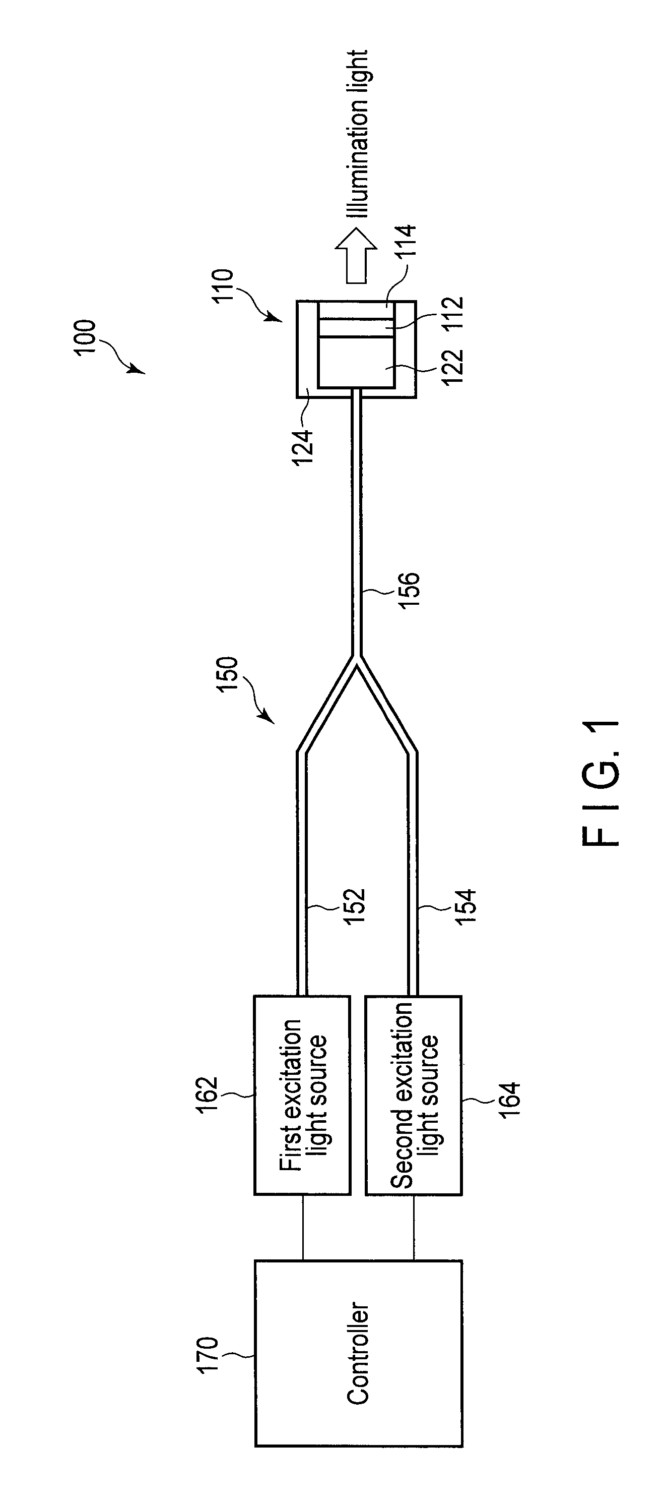
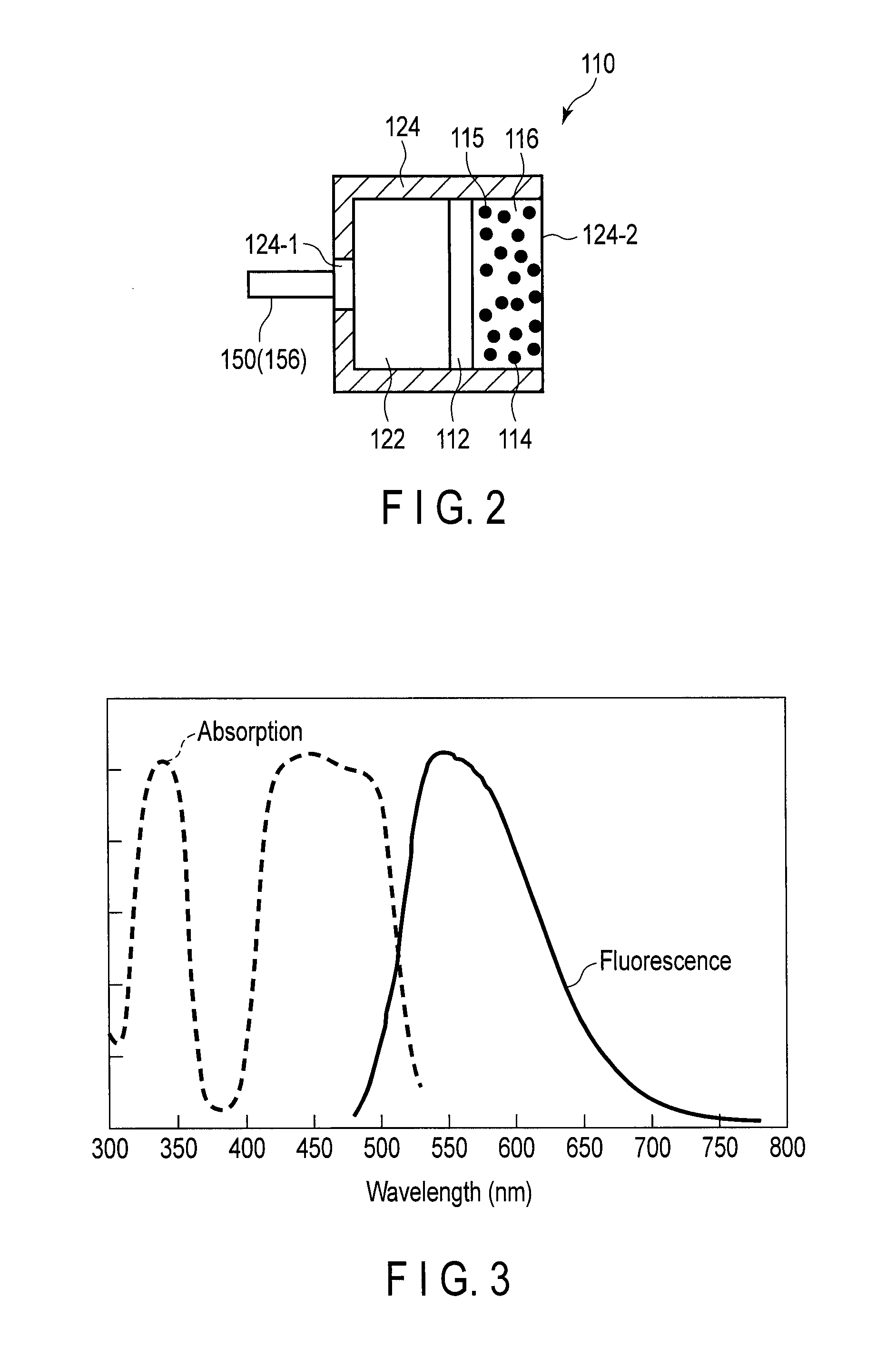
[0026]A first embodiment of the present invention is described with reference to the drawings. The schematic configuration of a light source device 100 according to the present embodiment is shown in FIG. 1. As shown in FIG. 1, the light source device 100 includes a wavelength converting unit 110, an optical coupler 150, a first excitation light source 162, a second excitation light source 164, and a controller 170.
[0027]The first excitation light source 162 is a light source which generates excitation light having a wavelength in a first wavelength region. In the present embodiment, the central wavelength in the first wavelength region is 450 nm, and the first excitation light source 162 is a blue laser diode (blue LD) which emits laser light having a wavelength of 450 nm. The excitation light emitted from the first excitation light source 162 is hereinafter referred to as first excitation light. The second excitation light source 164 is a light source which...
second embodiment
[0070][Second Embodiment]
[0071]A second embodiment is described. Here, parts different from those in the first embodiment are described, and the same parts are indicated by the same reference signs and are not described. A schematic configuration example of the wavelength converting unit 110 according to the present embodiment is shown in FIG. 10 and FIG. 11. FIG. 10 is a schematic diagram showing the cross section of the wavelength converting unit 110. FIG. 11 is a schematic diagram showing the plane of the wavelength converting unit 110 seen from the side of the emission opening.
[0072]As shown in FIG. 10 and FIG. 11, the second wavelength converting member 114 is disposed on the optical axes of the first excitation light and the second excitation light emitted from the emission end of the optical coupler 150 (the third optical fiber 156). The second wavelength converting member 114 is columnar. Here, as the divergence angles of the first excitation light and the second excitation ...
third embodiment
[0076][Third Embodiment]
[0077]A third embodiment is described. Here, parts different from those in the first embodiment are described, and the same parts are indicated by the same reference signs and are not described. A schematic configuration example of the wavelength converting unit 110 according to the present embodiment is shown in FIG. 12. As shown in FIG. 12, the light transmitting member 122, a third wavelength converting member 119, and the second wavelength converting member 114 are arranged in the holder 124 of the wavelength converting unit 110 in order in the traveling direction of the first excitation light and the second excitation light from the side of the emission end of the optical coupler 150.
[0078]An example of absorption / fluorescence characteristics of the third wavelength converting member 119 is shown in FIG. 13. As shown in FIG. 13, the third wavelength converting member 119 has the absorption characteristics for the wavelength region of the first excitation...
PUM
 Abstract
Description
Claims
Application Information
 - R&D
- Intellectual Property
- Life Sciences
- Materials
- Tech Scout
- Unparalleled Data Quality
- Higher Quality Content
- 60% Fewer Hallucinations
Browse by: Latest US Patents, China's latest patents, Technical Efficacy Thesaurus, Application Domain, Technology Topic, Popular Technical Reports.
© 2025 PatSnap. All rights reserved.Legal|Privacy policy|Modern Slavery Act Transparency Statement|Sitemap|About US| Contact US: help@patsnap.com


