Supercharge Your Innovation With Domain-Expert AI Agents!

Light source device

Active Publication Date: 2014-08-07
OLYMPUS CORP
View PDF5 Cites 13 Cited by
  • Summary
  • Abstract
  • Description
  • Claims
  • Application Information

AI Technical Summary

Benefits of technology

The present invention allows for adjusting the angle of the excitation light to create a light source with uniform light distribution. This results in better quality illumination.

Problems solved by technology

Thus, the illumination light emitted from such a light source device is unevenly colored light having a stronger excitation light component in the center and a weaker fluorescent component at the circumferential edge.

Method used


Image

  • Light source device
  • Light source device
  • Light source device

Examples


first embodiment

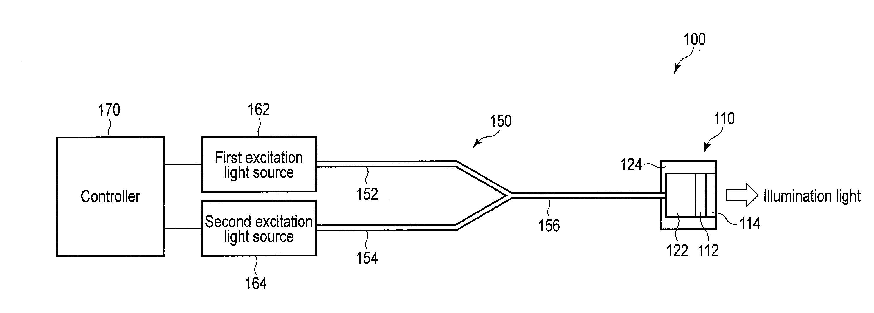
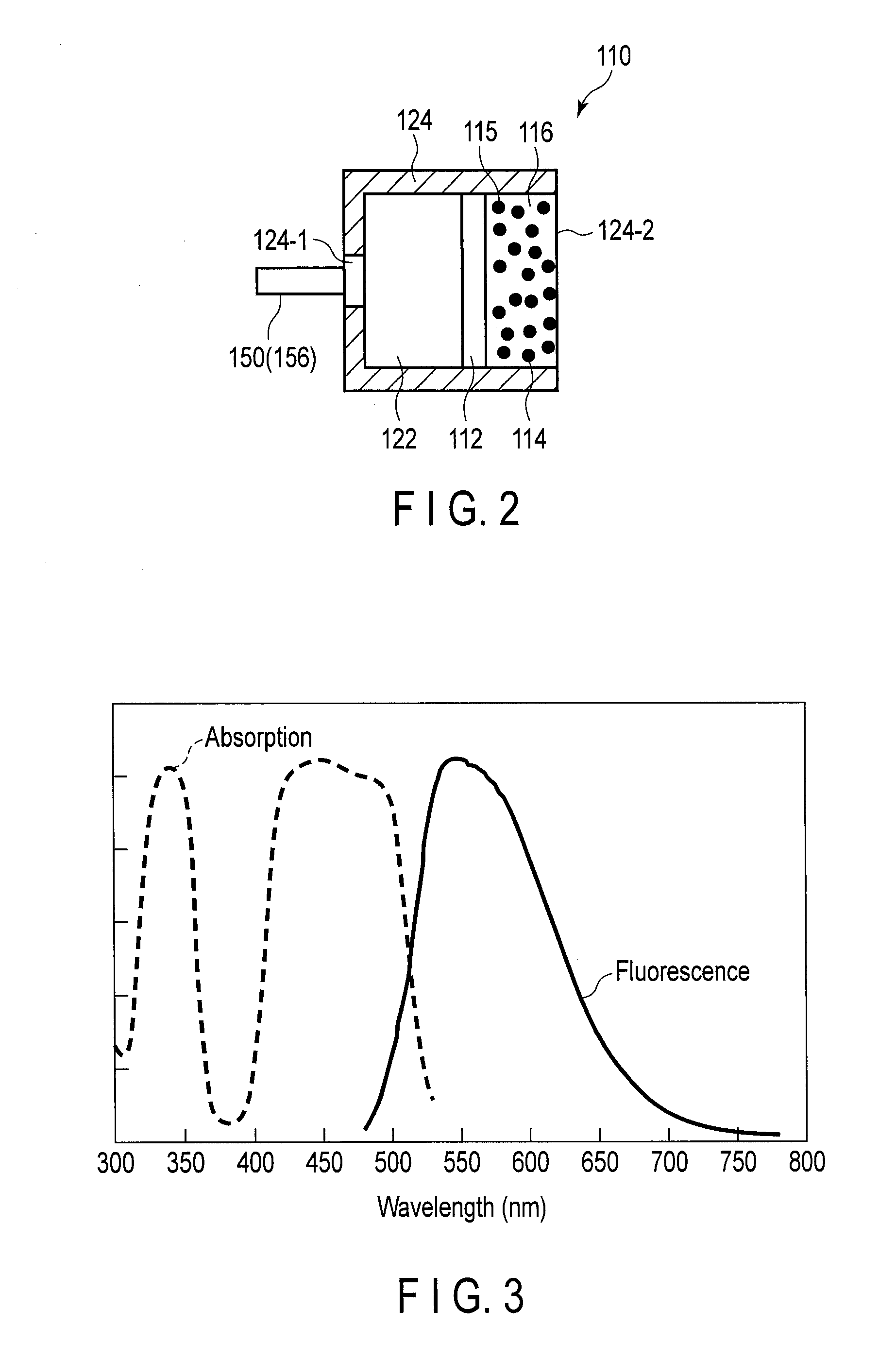
[0025]A first embodiment of the present invention is described with reference to the drawings. The schematic configuration of a light source device 100 according to the present embodiment is shown in FIG. 1. As shown in FIG. 1, the light source device 100 includes a wavelength converting unit 110, an optical coupler 150, a first excitation light source 162, a second excitation light source 164, and a controller 170.

[0026]The first excitation light source 162 is a light source which generates excitation light having a wavelength in a first wavelength region. In the present embodiment, the central wavelength in the first wavelength region is 450 nm, and the first excitation light source 162 is a blue laser diode (blue LD) which emits laser light having a wavelength of 450 nm. The excitation light emitted from the first excitation light source 162 is hereinafter referred to as first excitation light. The second excitation light source 164 is a light source which generates excitation li...

second embodiment

[0069]A second embodiment is described. Here, parts different from those in the first embodiment are described, and the same parts are indicated by the same reference signs and are not described. A schematic configuration example of the wavelength converting unit 110 according to the present embodiment is shown in FIG. 10 and FIG. 11. FIG. 10 is a schematic diagram showing the cross section of the wavelength converting unit 110. FIG. 11 is a schematic diagram showing the plane of the wavelength converting unit 110 seen from the side of the emission opening.

[0070]As shown in FIG. 10 and FIG. 11, the second wavelength converting member 114 is disposed on the optical axes of the first excitation light and the second excitation light emitted from the emission end of the optical coupler 150 (the third optical fiber 156). The second wavelength converting member 114 is columnar. Here, as the divergence angles of the first excitation light and the second excitation light are indicated by br...

third embodiment

[0074]A third embodiment is described. Here, parts different from those in the first embodiment are described, and the same parts are indicated by the same reference signs and are not described. A schematic configuration example of the wavelength converting unit 110 according to the present embodiment is shown in FIG. 12. As shown in FIG. 12, the light transmitting member 122, a third wavelength converting member 119, and the second wavelength converting member 114 are arranged in the holder 124 of the wavelength converting unit 110 in order in the traveling direction of the first excitation light and the second excitation light from the side of the emission end of the optical coupler 150.

[0075]An example of absorption / fluorescence characteristics of the third wavelength converting member 119 is shown in FIG. 13. As shown in FIG. 13, the third wavelength converting member 119 has the absorption characteristics for the wavelength region of the first excitation light and the wavelengt...


PUM


Abstract

A light source device includes a first excitation light source which emits first excitation light having a wavelength in a first wavelength region, a first optical member, a second optical member and a holding member which holds the first optical member and the second optical member. The first optical member converts at least part of the first excitation light to emit first wavelength converted light, and increase divergence angle of the transmitted first excitation light by a first incremental angle. A second optical member is disposed in a region including an optical axis of the first excitation light, and increases the divergence angle of the transmitted first excitation light by a second incremental angle larger than the first incremental angle.

Description

CROSS-REFERENCE TO RELATED APPLICATIONS[0001]This application is a Continuation Application of PCT Application No. PCT / JP2012 / 075993, filed Oct. 5, 2012 and based upon and claiming the benefit of priority from prior Japanese Patent Application No. 2011-224114, filed Oct. 11, 2011, the entire contents of all of which are incorporated herein by reference.BACKGROUND OF THE INVENTION[0002]1. Field of the Invention[0003]The present invention relates to a light source device.[0004]2. Description of the Related Art[0005]In general, there has been developed a light source device which emits light from a small solid-state light source, converts this light by a light converting member, and changes illumination light into a desired irradiation pattern or a desired color. For example, International Publication No. 2008 / 105527 discloses a light source device which is a combination of an LED chip disposed on a metallic substrate, a sealing resin sealing the LED chip, and a fluorescent material di...

Claims


Application Information

Patent Timeline
IPC IPC(8): F21V9/16
CPCF21V9/16A61B1/0638A61B1/0653F21V13/08F21Y2115/10F21Y2115/30F21V5/10F21V9/40G02B6/0008
Inventor TAMURA, KAZUAKIYAMAMOTO, EIJIITO, TAKESHI
Owner OLYMPUS CORP
Features
  • R&D
  • Intellectual Property
  • Life Sciences
  • Materials
  • Tech Scout
  • Unparalleled Data Quality
  • Higher Quality Content
  • 60% Fewer Hallucinations
Learn More