Supercharge Your Innovation With Domain-Expert AI Agents!

LED module and backlight unit having the same

a technology of led modules and backlight units, which is applied in the direction of instruments, lighting and heating apparatus, semiconductor devices for light sources, etc., can solve the problems of increasing the size of the display product area unnecessarily, increasing manufacturing costs, and dark parts

Inactive Publication Date: 2011-07-28
SAMSUNG ELECTRONICS CO LTD
View PDF37 Cites 39 Cited by
  • Summary
  • Abstract
  • Description
  • Claims
  • Application Information

AI Technical Summary

Benefits of technology

[0010]In addition, an aspect of the present invention provides an LED module capable of removing dark portions and implementing uniform light distribution characteristics by having directional angles widened in a lateral direction together with uniform line light source characteristics. In addition, an aspect of the present invention also provides a direct-type backlight unit capable of implementing uniform light distribution characteristics and being appropriate for an impulsive driving method by sequential lighting.

Problems solved by technology

A production display device has a bezel width having a predetermined size due to the required interval, which increases the size of the area of the display product unnecessarily, and thus a reduction thereof is required.
A great number of LEDs are required in order to obtain a uniform surface light source, such that it causes an increase in manufacturing costs.
When a small number of LEDs are used in order to reduce costs, dark portions or non-uniform color stains may be generated in a region between the LEDs.
However, in this case, the thickness of the display device becomes thick, thereby being disadvantageous in the realization of product slimness.

Method used


Image

  • LED module and backlight unit having the same
  • LED module and backlight unit having the same
  • LED module and backlight unit having the same

Examples


Embodiment Construction

[0031]Exemplary embodiments of the present invention will now be described in detail with reference to the accompanying drawings. The exemplary embodiments of the present invention may be modified in many different forms and the scope of the invention should not be limited to the embodiments set forth herein. In the drawings, the shapes and dimensions may be exaggerated for clarity, and the same reference numerals will be used throughout to designate the same or like components.

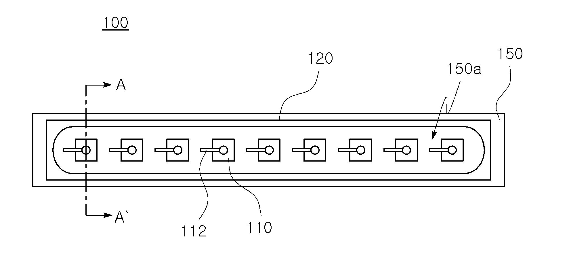
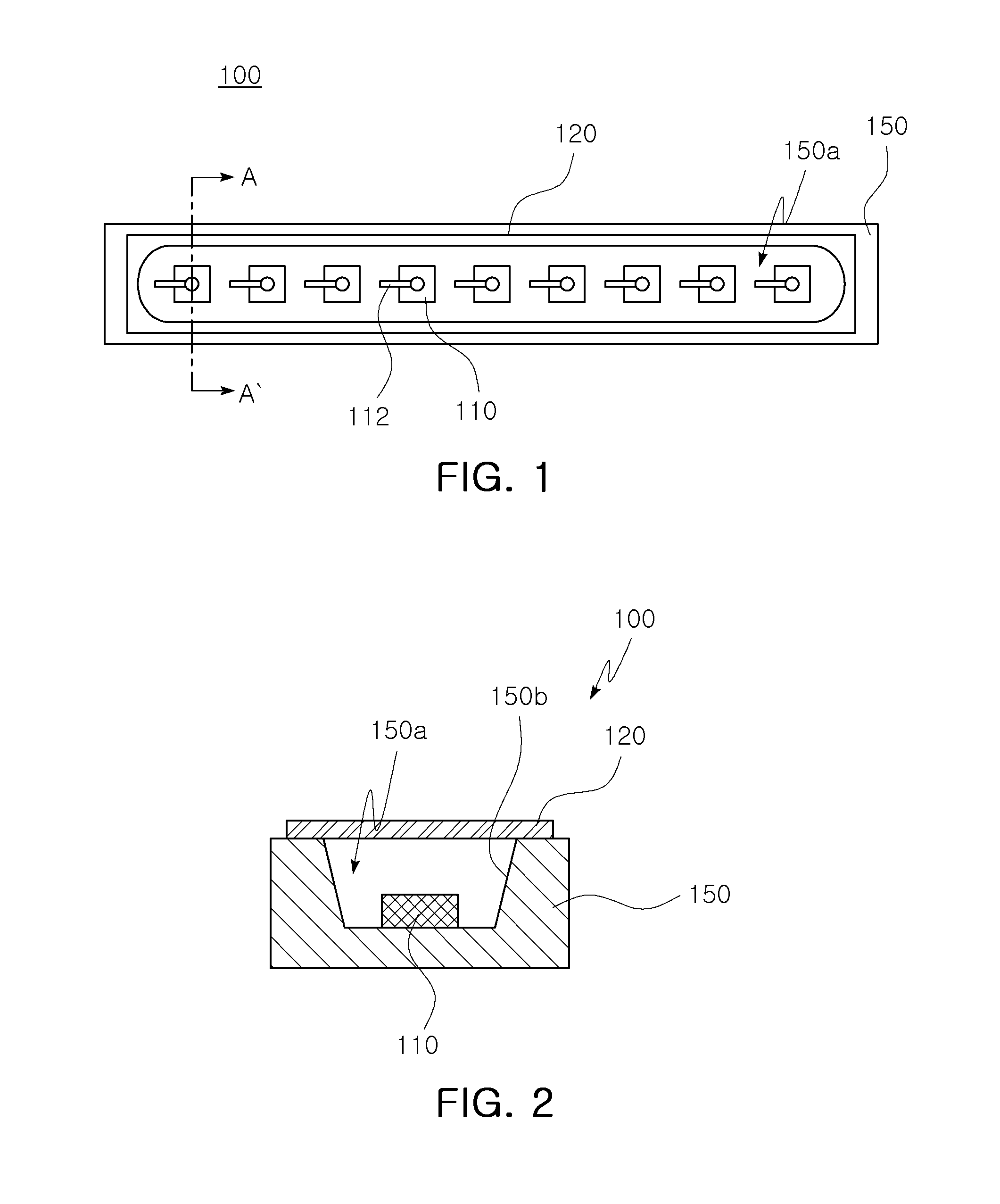
[0032]FIG. 1 is a plan view of an LED module that becomes a line light source according to an exemplary embodiment of the present invention and FIG. 2 is a cross-sectional view taken along line A-A′ of FIG. 1. Referring to FIGS. 1 and 2, an LED module 100 includes a circuit substrate 150 such as a lengthwise extended bar type PCB, a plurality of LED chips 110, and a phosphor film 120. As shown in FIG. 2, the circuit substrate 150 has a groove 150a on the upper portion thereof so as to have a reflecting cup, w...


PUM


Abstract

There is provided an LED module, including a bar type circuit substrate formed with at least one groove so as to have a reflecting cup; a plurality of LED chips disposed in the groove of the circuit substrate and linearly arranged in a longitudinal direction of the circuit substrate; and a phosphor film spaced apart from the LED chips and disposed on the circuit substrate to cover the entire groove.

Description

CROSS-REFERENCE TO RELATED APPLICATIONS[0001]This application claims the priority of Korean Patent Application No. 2010-0007064 filed on Jan. 26, 2010, in the Korean Intellectual Property Office, the disclosure of which is incorporated herein by reference.BACKGROUND OF THE INVENTION[0002]1. Field of the Invention[0003]The present invention relates to an LED module and a backlight unit having the same, and more particularly, to an LED module in a line light source and a backlight unit having the same.[0004]2. Description of the Related Art[0005]With the recent trend for slimness and high performance in an image display device, a liquid crystal display device (LCD device) has been widely used in TVs, computer monitors, and the like. A liquid crystal panel cannot emit light by itself, such that it requires a separate light source unit, that is, a backlight unit (hereinafter, referred to as a ‘BLU’). As a BLU light source, a cold cathode fluorescent lamp (CCFL) has previously been used....

Claims


Application Information

Patent Timeline
IPC IPC(8): F21V8/00H01L33/08G02F1/13357
CPCF21K9/00F21S4/008F21Y2101/02F21Y2103/003H01L25/0753H01L2924/0002H01L33/505H01L33/58H01L2924/00F21S4/28F21Y2103/10F21Y2115/10G02F1/133615
Inventor KO, KUN YOOCHOI, SEUNG HWANLEE, WON JOONKIM, JIN MO
Owner SAMSUNG ELECTRONICS CO LTD
Features
  • R&D
  • Intellectual Property
  • Life Sciences
  • Materials
  • Tech Scout
  • Unparalleled Data Quality
  • Higher Quality Content
  • 60% Fewer Hallucinations
Learn More