Display Device Uniforming Light Distribution Throughout Areas and Method for Manufacturing Same

a technology of optical display and uniform light distribution, which is applied in the direction of instruments, other domestic objects, mechanical instruments, etc., can solve the problems of affecting the quality of the image, so as to achieve uniform luminance over the entire screen, avoid the effect of peripheral luminance degradation, and reduce the gradient of sidewall waveguides

Active Publication Date: 2008-10-23
SEKONIX
View PDF6 Cites 18 Cited by
  • Summary
  • Abstract
  • Description
  • Claims
  • Application Information

AI Technical Summary

Benefits of technology

[0018]As described above, in the present invention, the sidewall gradient of waveguides is designed to be different in the central and peripheral areas of a screen in such a way as to be gradually decreased radially away from the central area towards the peripheral area. Thus, degradation in the peripheral luminance can be avoided. In addition, the sidewall gradient of waveguides is gradually decreased from the central area of a screen in a horizontal or vertical direction towards the peripheral area, thereby achieving uniform luminance over the entire screen.
[0019]Furthermore, the size, height, spacing, and refraction index of waveguides are designed to be different for each section, depending on incident angle and / or intensity of light inputted from a light source. Therefore, a uniform light distribution can be achieved over the whole area of the optical device, and homogeneity in the projected image can be consequently enhanced.
[0020]In addition, a low index resin is filled in the valley-like space between the waveguides and a light diffuser is added to the low index region, thereby further improving the uniform light distribution. Here, the mated particle size, and contents of the light diffuser can be controlled to adjust the light distribution.

Problems solved by technology

However, the luminance in the peripheral area is considerably degraded relative to the central area of the screen.
For this reason, the image distinctiveness and clarity are made different in the central and peripheral areas of the screen, and homogeneity in the image is consequently degraded, thereby failing to achieve a high quality image.
In particular, a large-scale display device employs a plurality of unit light sources or a single diffusive light source, and the light intensity thus becomes non-uniform throughout the screen.
For the above reasons, the brightness is not uniform over the entire screen, consequently resulting in non-uniform image distinctiveness and clarity, and degraded image resolution.

Method used


Image

  • Display Device Uniforming Light Distribution Throughout Areas and Method for Manufacturing Same
  • Display Device Uniforming Light Distribution Throughout Areas and Method for Manufacturing Same
  • Display Device Uniforming Light Distribution Throughout Areas and Method for Manufacturing Same

Examples


first embodiment

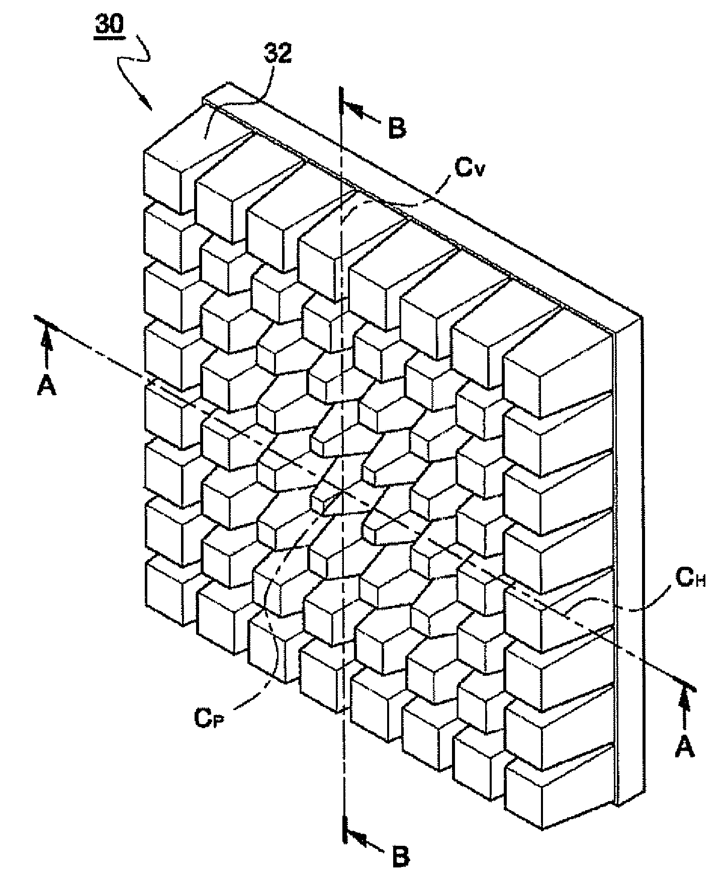
[0061]FIG. 5 is a sectional view of an optical display device producing a uniform light distribution according to the invention, where the invention is applied to a projection screen. In FIG. 5, the projection screen of the invention is generally denoted at 1. FIGS. 6 to 8 show one example for the configuration of the waveguides in the optical display device in FIG. 5. FIG. 6 is a perspective view of the waveguide array, FIG. 7 is a sectional view taken along the line A-A in FIG. 6, and FIG. 8 is a sectional view taken along the line B-B in FIG. 6.

[0062]As illustrated in FIG. 5, the projection screen 1 of this embodiment includes a front transparent plate 10, a rear transparent substrate 20, and a waveguide array 30 interposed in-between. A unit waveguide 32 (hereinafter, referred to as a “waveguide”) is structured to have a smaller bottom face to a light source 40 side and a larger top face contacted with the front transparent plate 10. That is, the waveguide 32 is structured such ...

second embodiment

[0081]FIGS. 14 and 15 are a front and rear perspective view of an optical display device producing a uniform light distribution according to the invention. FIG. 16 is a sectional view taken along the line D-E in FIG. 14, and FIG. 17 is a partial sectional view of a modified example of FIG. 16. In this embodiment, the waveguides have a uniform height. In addition, the optical device according to the invention may or may not be provided with a transparent protection plate attached to the front face or the rear face thereof. The following embodiments illustrate cases having no transparent protection plate attached thereto, and are referred to as an “optical device.”

[0082]In the optical display device 110 of this embodiment, the waveguide 112 has a truncated conical shape whose cross-sectional area gradually decreases towards the light output surface thereof. These waveguides are arranged in vertical and horizontal directions. In particular, the height of the waveguide 112 is uniform ov...

third embodiment

[0100]FIGS. 29 and 30 are a front and rear perspective view of an optical display device producing a uniform light distribution according to the invention. FIG. 31 is a sectional view ten along the line F-F in FIG. 29. This embodiment illustrates a case of waveguides having non-uniform heights.

[0101]In this embodiment, the height of the waveguides 112′ in the optical device 110′ is not uniform, but increases gradually towards the peripheral area of the device from the central area thereof. More specifically, as shown in FIG. 31, the height of the peripheral waveguide 112f in the optical device 110′ is higher than that of the central waveguide 112a′, in such a manner that the peripheral waveguides surround the central waveguides. The sidewall gradient is almost the same in all the waveguides 112′. The bottom side and the topside of the waveguides 112′ are gradually increased the farther away they are from the center of the optical device 110′. Consequently, the size of the waveguides...


PUM

PropertyMeasurementUnit
critical angleaaaaaaaaaa

Abstract

Disclosed arm an optical display device producing uniform light distribution and a method of fabricating such devices. The optical display device has waveguides arranged in vertical and horizontal directions. The waveguide has a conical shape whose cross-section decreases towards the light-projection side thereof. At least one of the size, height, spacing, and refraction index of the waveguide is designed to be different for each section, depending on an incident angle and/or intensity of light inputted from a light source. Therefore, the intensity of projected light can be made uniform over all sections of the optical device.

Description

TECHNICAL FIELD[0001]The present invention relates to an optical display device producing a uniform light distribution over the entire area. More specifically, the invention relates to such devices and a method of fabricating the same, in which the size, the height, the spacing, and the refraction index of waveguides are all designed to be different for each section, depending on an incident angle and / or light intensity inputted from a light source, and thus a uniform light distribution can be achieved over the whole area of the optical device while maintaining a desired viewing angle, and the luminance in the peripheral area of the device can be avoided from being degraded.BACKGROUND ART[0002]In general, a projection device such as a projection TV, a projection monitor, or the like is equipped with a rear projection screen projecting images toward the viewer's side. This rear projection screen is one of the optical display devices designed such that the images projected from the re...

Claims


Application Information

Patent Timeline
Patent Type & Authority Applications(United States)
IPC IPC(8): G02B6/08B29D11/00G02B6/04F21V8/00G02B27/09
CPCG02B6/0053G02B6/0065G02F1/133524G02F2001/133562G02F1/133562
Inventor HWANG, GYUHWANYU, YOUNGBINLEE, HYUNSOO
Owner SEKONIX
Why Eureka
Try Eureka