Backlighting array supporting adaptable parallax barrier

a backlighting array and parallax barrier technology, applied in the field of display systems, can solve the problems of unsatisfactory viewing experience for viewers, headaches and nausea, and disparity in perceived brightness between the different simultaneously-displayed regions

Inactive Publication Date: 2011-06-30
AVAGO TECH WIRELESS IP SINGAPORE PTE
View PDF105 Cites 73 Cited by
  • Summary
  • Abstract
  • Description
  • Claims
  • Application Information

AI Technical Summary

Benefits of technology

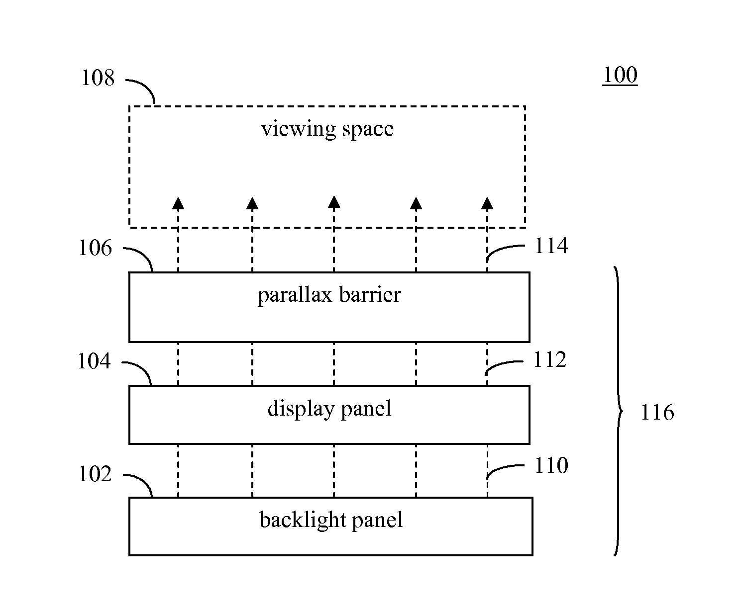
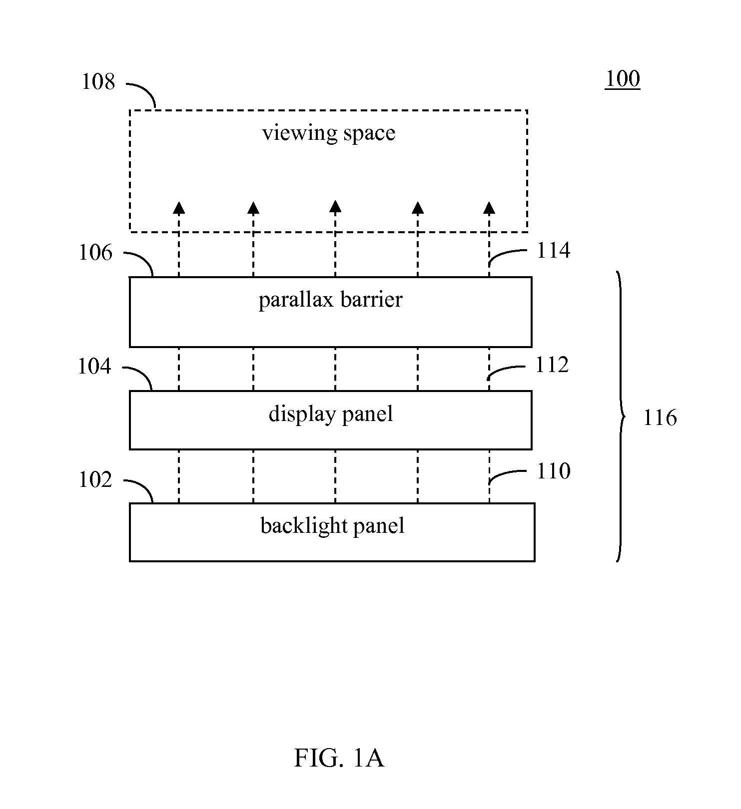
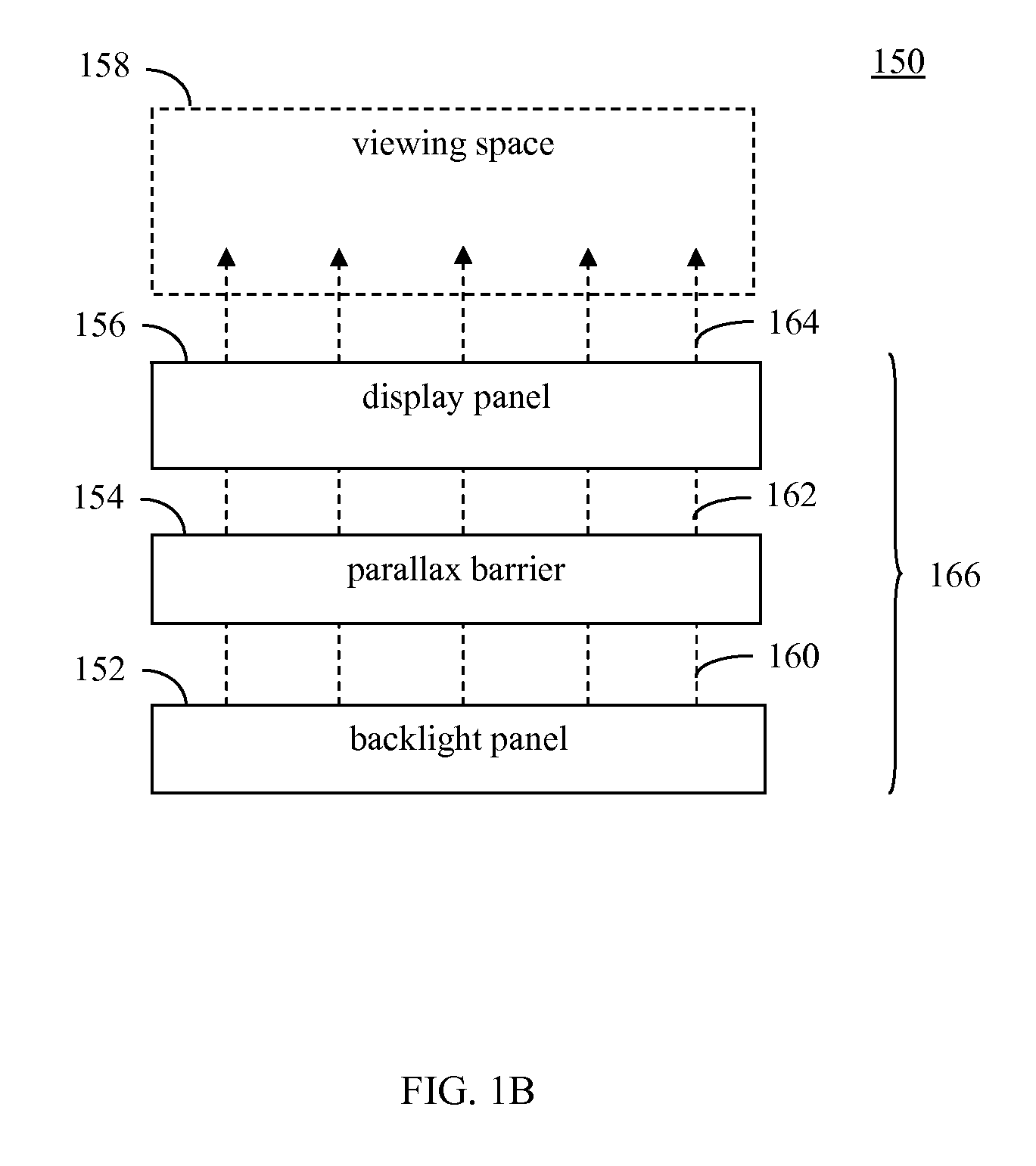
[0012]Display systems and methods are described herein. In accordance with certain embodiments, the display systems and methods provide a backlight panel comprising an array of light sources (e.g., LEDs) that may be individually controlled to vary the backlighting luminosity provided to a proximately-positioned display panel on a region-by-region basis. Such control may be automatic and / or manual. This enables, for example, the brightness of each region to be controlled such that a viewer perceives roughly uniform brightness across all regions. This is particularly useful in a display system having an adaptable parallax barrier that allows for the simultaneous viewing of two-dimensional images, three-dimensional images and multi-view three-dimensional content in different display regions, since those display regions may be perceived as having a different number of pixels per unit area.

Problems solved by technology

A disadvantage of parallax barriers is that the viewer must be positioned in a well-defined location in order to experience the three-dimensional effect.
If the viewer moves his / her eyes away from this “sweet spot,” image flipping and / or exacerbation of the eyestrain, headaches and nausea that may be associated with prolonged three-dimensional image viewing may result.
When simultaneously displaying two-dimensional, three-dimensional and multi-view three-dimensional regions using a system such as that described in above-reference U.S. patent application Ser. No. 12 / 845,440, the use of a conventional backlight will result in a disparity in perceived brightness between the different simultaneously-displayed regions.
This disparity in perceived brightness between display regions may lead to an unsatisfactory viewing experience for a viewer.
For example, when the viewer adjusts the brightness level of the backlight to improve the appearance of an image in a particular region, the viewer may also cause the brightness of an image in another display region to be reduced or increased to an undesired level.
Consequently, the viewer will be unable to set all of the display regions to a single desired brightness level.
In addition, the viewer may be unable to adequately perceive images displayed in regions of reduced brightness.
Furthermore, the disparity in perceived brightness between the display regions may be distracting or annoying to the viewer.

Method used


Image

  • Backlighting array supporting adaptable parallax barrier
  • Backlighting array supporting adaptable parallax barrier
  • Backlighting array supporting adaptable parallax barrier

Examples


Embodiment Construction

I. Introduction

[0049]The present specification discloses one or more embodiments that incorporate the features of the invention. The disclosed embodiment(s) merely exemplify the invention. The scope of the invention is not limited to the disclosed embodiment(s). The invention is defined by the claims appended hereto.

[0050]References in the specification to “one embodiment,”“an embodiment,”“an example embodiment,” etc., indicate that the embodiment described may include a particular feature, structure, or characteristic, but every embodiment may not necessarily include the particular feature, structure, or characteristic. Moreover, such phrases are not necessarily referring to the same embodiment. Further, when a particular feature, structure, or characteristic is described in connection with an embodiment, it is submitted that it is within the knowledge of one skilled in the art to effect such feature, structure, or characteristic in connection with other embodiments whether or not ...


PUM


Abstract

Display systems are described that include an adaptable parallax barrier that filters light passed by a display panel in a manner that allows for the simultaneous viewing of two-dimensional images, three-dimensional images and multi-view three-dimensional content in different display regions. The display system also includes a backlight panel comprising an array of light sources that may be individually controlled to vary the backlighting luminosity provided to the display panel on a region-by-region basis. Since each of the display regions may be perceived as having a different number of pixels per unit area depending upon the type of content being presented, the backlight array enables the brightness of each region to be controlled such that a viewer perceives roughly uniform brightness across all regions. Alternative regional brightness control schemes are also described.

Description

CROSS-REFERENCE TO RELATED APPLICATIONS[0001]This application claims the benefit of U.S. Provisional Application No. 61 / 291,818, filed on Dec. 31, 2009, which is incorporated by reference herein in its entirety. This application also claims the benefit of U.S. Provisional Application No. 61 / 303,119, filed on Feb. 10, 2010, which is incorporated by reference herein in its entirety.[0002]This application is also related to the following U.S. patent applications, each of which also claims the benefit of U.S. Provisional Patent Application Nos. 61 / 291,818 and 61 / 303,119 and each of which is incorporated by reference herein:[0003]U.S. patent application Ser. No. 12 / 845,409, filed on Jul. 28, 2010, and entitled “Display with Adaptable Parallax Barrier”; and[0004]U.S. patent application Ser. No. 12 / 845,440, filed on Jul. 28, 2010, and entitled “Adaptable Parallax Barrier Supporting Mixed 2D and Stereoscopic 3D Display Regions.”BACKGROUND OF THE INVENTION[0005]1. Field of the Invention[0006...

Claims


Application Information

Patent Timeline
Patent Type & Authority Applications(United States)
IPC IPC(8): G09G5/10
CPCG06F3/14G06F3/0346G09G3/20G09G5/003G09G5/14G09G2300/023G09G2320/028G09G2370/04H04N13/0029H04N13/0048H04N13/0055H04N13/0059H04N13/0404H04N13/0409H04N13/0411H04N13/0447H04N13/0454H04N13/0456H04N13/0468H04N13/0497H04N21/235H04N21/4122H04N21/435H04N2013/0463H04N2013/0465G03B35/24H04N13/0413H04N13/0429H04N13/0484H04S7/303G09G3/003H04N13/361G02B6/00H04N13/00H04N13/139H04N13/161H04N13/189H04N13/194H04N13/305H04N13/31H04N13/312H04N13/315H04N13/332H04N13/351H04N13/359H04N13/366H04N13/383H04N13/398H04N2013/403H04N2013/405
Inventor BENNETT, JAMES D.KARAOGUZ, JEYHAN
Owner AVAGO TECH WIRELESS IP SINGAPORE PTE
Why Eureka
Try Eureka