Spread illuminating apparatus of multiple panel type

a technology of illumination apparatus and spread light, which is applied in the direction of lighting and heating apparatus, planar/plate-like light guides, instruments, etc., can solve the problems of insufficient size and shape of areas which are allowed to be area controlled, inability to achieve a backlight suitably matching a pseudo impulse driving, and inability to achieve photoelectric conversion efficiency, etc., to achieve enhanced and uniform brightness, reduce power consumption, and effectively use stray light

Inactive Publication Date: 2008-05-01
MINEBEA CO LTD
View PDF2 Cites 77 Cited by
  • Summary
  • Abstract
  • Description
  • Claims
  • Application Information

AI Technical Summary

Benefits of technology

[0021]The present invention has been made in light of the problems described above, and it is an object of the present invention to provide a spread illuminating apparatus of multiple panel type, in which the brightness can be surely kept uniform without influence of stray light while avoiding an increase in power consumption.
[0023]Since the spread illuminating apparatus includes the plurality of lighting units arranged two dimensionally, a large luminous area is provided thus constituting a backlight suitable for a large LCD. Also, due to the overhang which is located between the light inlet surface of a lighting unit and the opposite end surface of an adjacent lighting unit so as to cover the light outlet surface side face of the light source of the lighting unit, and which, unlike a cover film conventionally used to deal with stray light from the light source, does not shield or reflect light but effectively utilizes stray light by diffusing and allowing light to exit from the light outlet surface, and due to the lighting diffusing means disposed at the overhang, the brightness can be surely enhanced in a uniform manner without increasing power consumption on the light source.
[0026]Accordingly, the spread illuminating apparatus of multiple panel type according to the present invention surely achieves an enhanced and uniform brightness by effectively using stray light while reducing power consumption.

Problems solved by technology

Conventional backlights, however, have the following difficulties in keeping up with the aforementioned improvement of image quality and enhancement of performance.
In a direct light type backlight with CCFLs, since a CCFL has a low response speed, and since the number of CCFLs provided in a backlight is usually restricted, commonly it is difficult to achieve a backlight to suitably match a pseudo impulse driving (especially, the above-described black insertion driving method).
Also, in a direct light type backlight with CCFLs, the luminous region cannot be divided into individual areas in the direction orthogonal to the length of the CCFLs because of its structure, and therefore the areas which are allowed to be area-controlled tend to be very inadequate in size and shape.
However, the photoelectric conversion efficiency is low in achieving a white light by mixing lights from red, green and blue LEDs, thus raising problems with power consumption, heat value from light sources, cost, and the like for achieving a white light with an adequate brightness.
The edge light type backlight as a lighting unit, however, has a peculiar problem that light leakage occurs such that a ball-shaped light called “hotspot” leaks from an LED package and becomes what is called a “stray light” to be viewable from the side of the light outlet surface of the backlight, which degrades the quality of the light of the backlight.
This solution, however, cannot be applied to the multiple panel type backlight which includes a plurality of lighting units arranged two dimensionally so as to cover a large LCD panel.
That is to say, it is not possible for the non-effective areas of all the lighting units to be located outside the display area of the LCD.
So, the brightness of the LED 14 must be increased in order to provide a sufficient brightness for the multiple panel backlight 10, which results in an increased power consumption.
The utilization efficiency, however, is low, and the brightness of the LED 14 must be increased in order to provide a sufficient brightness for the multiple panel backlight 10, thus inevitably increasing power consumption.

Method used


Image

  • Spread illuminating apparatus of multiple panel type
  • Spread illuminating apparatus of multiple panel type
  • Spread illuminating apparatus of multiple panel type

Examples


Embodiment Construction

[0032]An exemplary embodiment of the present invention will hereinafter be described with reference to the accompanying drawings, wherein any components identical with or corresponding to those of the aforementioned conventional art are denoted by the same reference numerals, and a detailed description thereof will be omitted below.

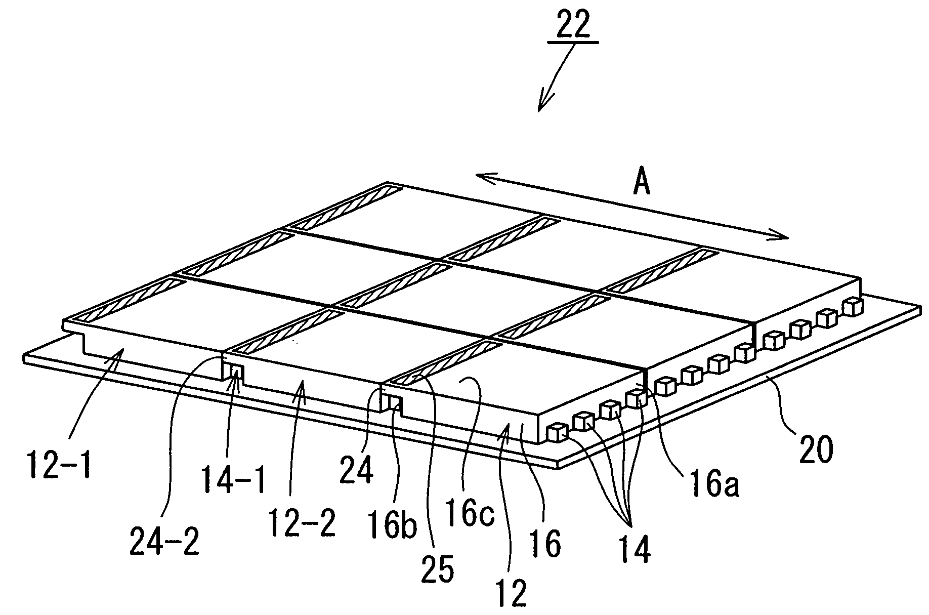
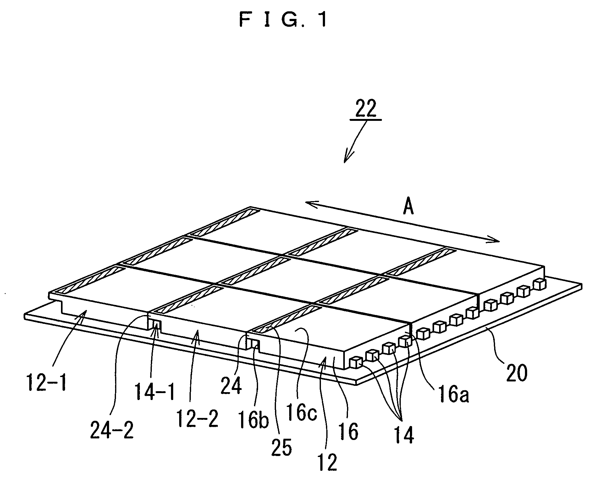
[0033]Referring to FIG. 1, a spread illuminating apparatus of multiple panel type (hereinafter referred to simply as “spread illuminating apparatus” as appropriate) 22 according to an embodiment of the present invention includes a plurality of lighting units 12 which each include light sources (for example, LEDs) 14 and a light conductor plate 16, and which are arranged two dimensionally.

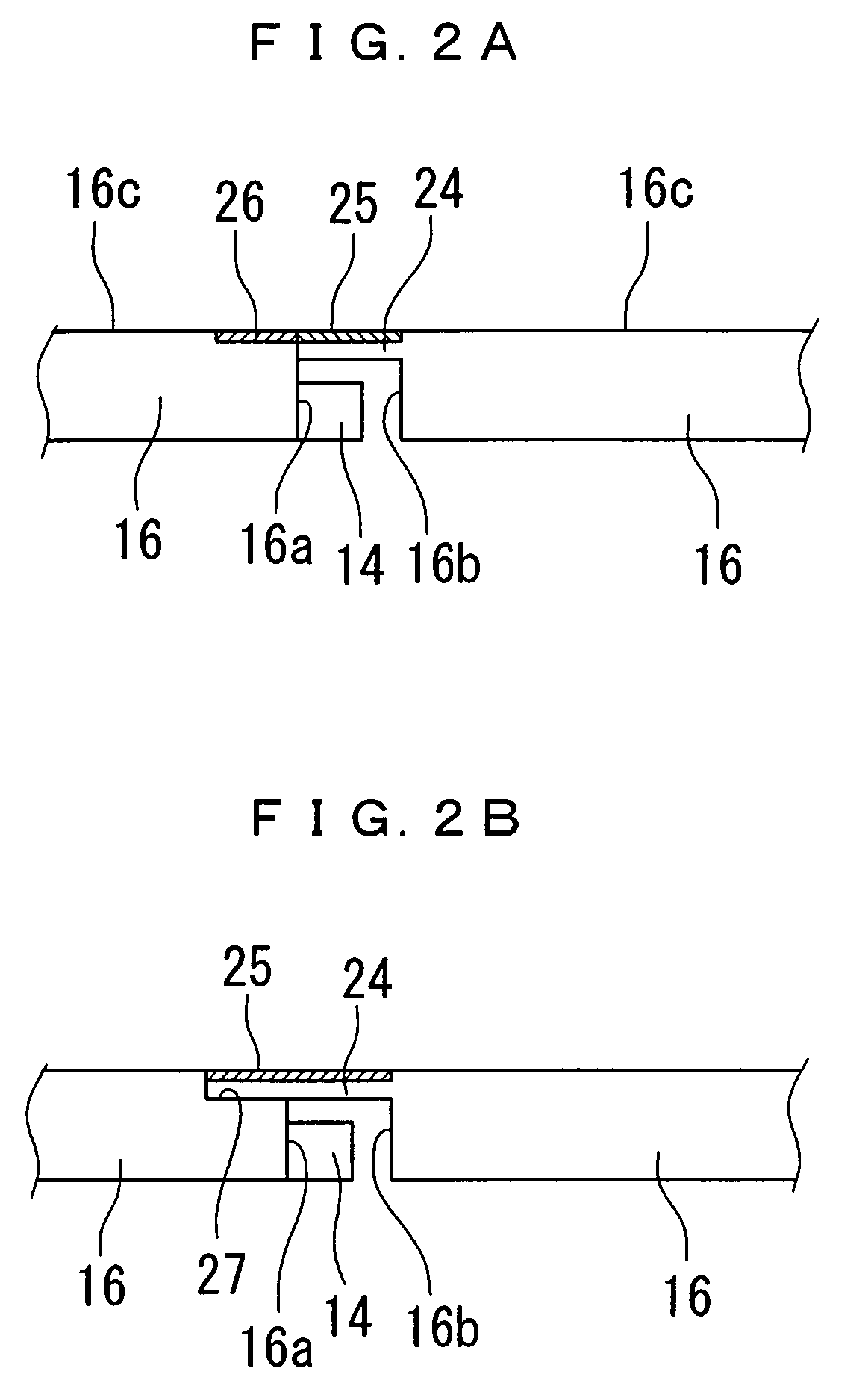
[0034]The light conductor plate 16 includes a light inlet surface 16a at which the light sources 14 are disposed, an end surface 16b (hereinafter referred to as “opposite end surface” as appropriate) opposite to the light inlet surface 16a, and a major surface 16c defined...


PUM


Abstract

A spread illuminating apparatus includes a plurality of lighting units which are arranged two dimensionally, and each of which includes light sources and a light conductor plate which has a light inlet surface having the light sources disposed thereat, an opposite end surface opposite to the light inlet surface, and a major surface defined as a light outlet surface for the lighting unit, wherein an overhang is formed integrally with the light conductor plate so as to protrude from the opposite end surface, and wherein every two adjacent lighting units of the plurality of lighting units are jointed to each other such that the light outlet surface side face of the light source of the lighting unit is covered by the overhang, and wherein a light diffusing means is disposed at a side surface of the overhang positioned toward the light outlet surface.

Description

BACKGROUND OF THE INVENTION[0001]1. Field of the Invention[0002]The present invention relates to a spread illuminating apparatus suitable for use as backlight unit of a liquid crystal display device.[0003]2. Description of the Related Art[0004]A liquid crystal display (LCD) device is used extensively as a display device for various electronic devices and recently is increasingly superseding a cathode ray tube (CRT) also in a relatively large display device as typified by, for example, a personal computer and a TV set.[0005]For such a large LCD device, a direct light type backlight has been conventionally predominant which is structured such that a plurality of cold cathode lamps (hereinafter referred to as CCFLs as appropriate) as light sources are disposed immediately beneath an LCD panel, and in which light is condensed by an optical sheet and light intensity is uniformed by a diffuser sheet (refer to, for example, Japanese Patent No. 3653274).[0006]Recently, various approaches to...

Claims


Application Information

Patent Timeline
Patent Type & Authority Applications(United States)
IPC IPC(8): F21V5/00
CPCG02B6/0068G02B6/0078G02F1/133615G02B6/0088G02F1/133611G02B6/008
Inventor KITAMURA, ATSUSHIADACHI, SHIGEYUKI
Owner MINEBEA CO LTD
Why Eureka
Try Eureka