Liquid crystal display and light guide plate thereof

A liquid crystal display and light guide plate technology, applied in the field of light guide plates, can solve problems such as large refractive index and uneven light distribution, and achieve the effect of uniform light distribution

Inactive Publication Date: 2010-06-02
AU OPTRONICS CORP
View PDF0 Cites 20 Cited by
  • Summary
  • Abstract
  • Description
  • Claims
  • Application Information

AI Technical Summary

Problems solved by technology

However, because the refractive index of the light guide plate is higher than that of the air layer, under the influence of the light refraction effect, after the LED light enters the light guide plate, the light from the LED will be collected in the area adjacent to the light incident surface of the light guide plate. The angle range is small, so it is easy to appear a dark area with

Method used


Image

  • Liquid crystal display and light guide plate thereof
  • Liquid crystal display and light guide plate thereof
  • Liquid crystal display and light guide plate thereof

Examples


Example Embodiment

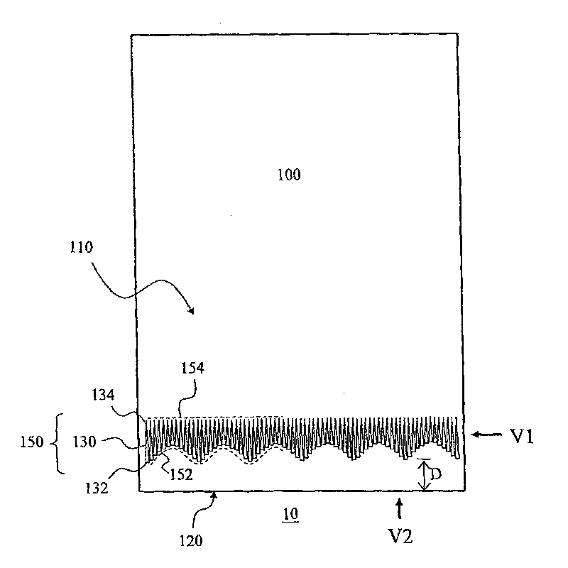
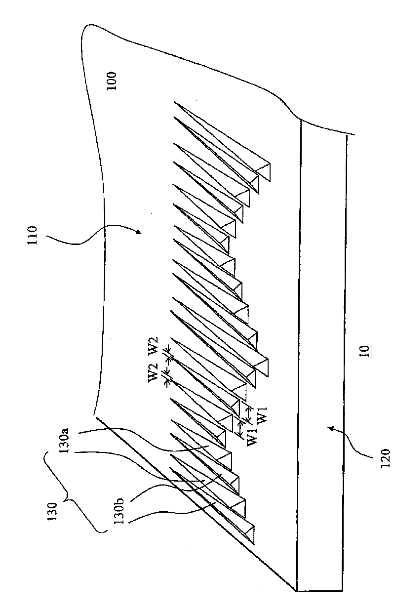
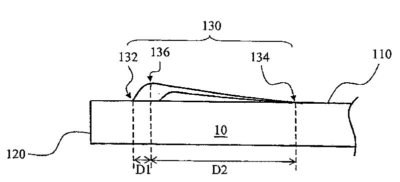
[0063] Please refer to figure 1 , is a top view of a light guide plate according to an embodiment of the present invention. like figure 1 As shown, the light guide plate 10 of the present invention at least includes a main body 100 and a microstructure module 150. The main body 100 has a light exit surface 110 and a light entrance surface 120. The light entrance surface 120 is connected to the light exit surface 110. For example: the light entrance surface 120 is Intersect with the light-emitting surface 110 at right angles. The microstructure module 150 is composed of a plurality of microstructures 130, such as: cone-shaped microstructures, semi-cylindrical dimensional structures, semi-ellipsoidal microstructures, or prismatic dimensional structures, etc., which are arranged on the light-emitting surface 110 and adjacent to the entrance Glossy 120. The connecting line 152 of the plurality of microstructures 130 near the first end 132 of the light incident surface 120 is a ...


PUM


Abstract

The invention discloses a liquid crystal display and a light guide plate thereof. The light guide plate has a light leaving surface and a light incident surface; a microstructure module is arranged on the light leaving surface in a direction that the microstructure module directly faces the light incident surface; the microstructure module comprises a plurality of alternately arranged conical microstructures; and one end of each microstructure is narrower than the other end of the microstructure. The line connecting the end point of one end of each microstructure is a curve, and the line connecting the end point of the other end of each microstructure is a straight line or a curve.

Description

technical field [0001] The invention relates to a light guide plate, in particular to a light guide plate suitable for a liquid crystal display panel. Background technique [0002] The liquid crystal display is not a display device capable of self-illumination. It mainly uses the light emitted by an external light source to pass through the display panel to illuminate the liquid crystal display. Therefore, an external light source and a corresponding light guide device, such as a backlight module, are usually required to illuminate the liquid crystal display. The emitted light is directed to the display panel. [0003] At present, light emitting diodes (Light Emitting Diodes, LEDs) are mostly used as light sources for backlight modules of liquid crystal displays due to their characteristics of low operating voltage, high luminance, fast response speed, and long lifespan. However, the outgoing light emitted by the light-emitting diode has strong optical directivity, that is,...

Claims


Application Information

Patent Timeline
IPC IPC(8): F21V8/00G02F1/13357G02F1/1333
Inventor 简智伟张维典蔡卲瑜
Owner AU OPTRONICS CORP
Why Eureka
Try Eureka