Diffusion plate with at least one star diffusion structure and a lighting module using the same

a diffusion structure and diffusion plate technology, applied in the field of diffusion plates, can solve the problems of increasing the thickness and the cost of the backlight module, the insufficient light distribution uniformity of the conventional the total cost of the direct lighting-type backlight module, so as to improve the light distribution uniformity of the lighting module

Active Publication Date: 2012-06-12
AU OPTRONICS CORP
View PDF13 Cites 19 Cited by
  • Summary
  • Abstract
  • Description
  • Claims
  • Application Information

AI Technical Summary

Benefits of technology

[0006]It is an object of the present invention to provide a diffusion plate for use with a lighting module to enhance the light distribution uniformity of the lighting module.
[0007]It is another object of the present invention to provide a diffusion plate for use with a lighting module to decrease the manufacturing cost of the lighting module.
[0008]It is a further object of the present invention to provide a lighting module having improved light distribution uniformity.
[0009]It is yet another object of the present invention to provide a lighting module having reduced manufacturing cost.

Problems solved by technology

However, though a double-layer structure is used, the conventional direct lighting-type backlight module still has insufficient light distribution uniformity.
Using double-layer structure or more layers of optical films to maintain certain degree of light distribution uniformity will increase the thickness and the cost of the backlight module.
Therefore, LEDs have a significant contribution to the total cost of the direct lighting-type backlight module.

Method used


Image

  • Diffusion plate with at least one star diffusion structure and a lighting module using the same
  • Diffusion plate with at least one star diffusion structure and a lighting module using the same
  • Diffusion plate with at least one star diffusion structure and a lighting module using the same

Examples


Embodiment Construction

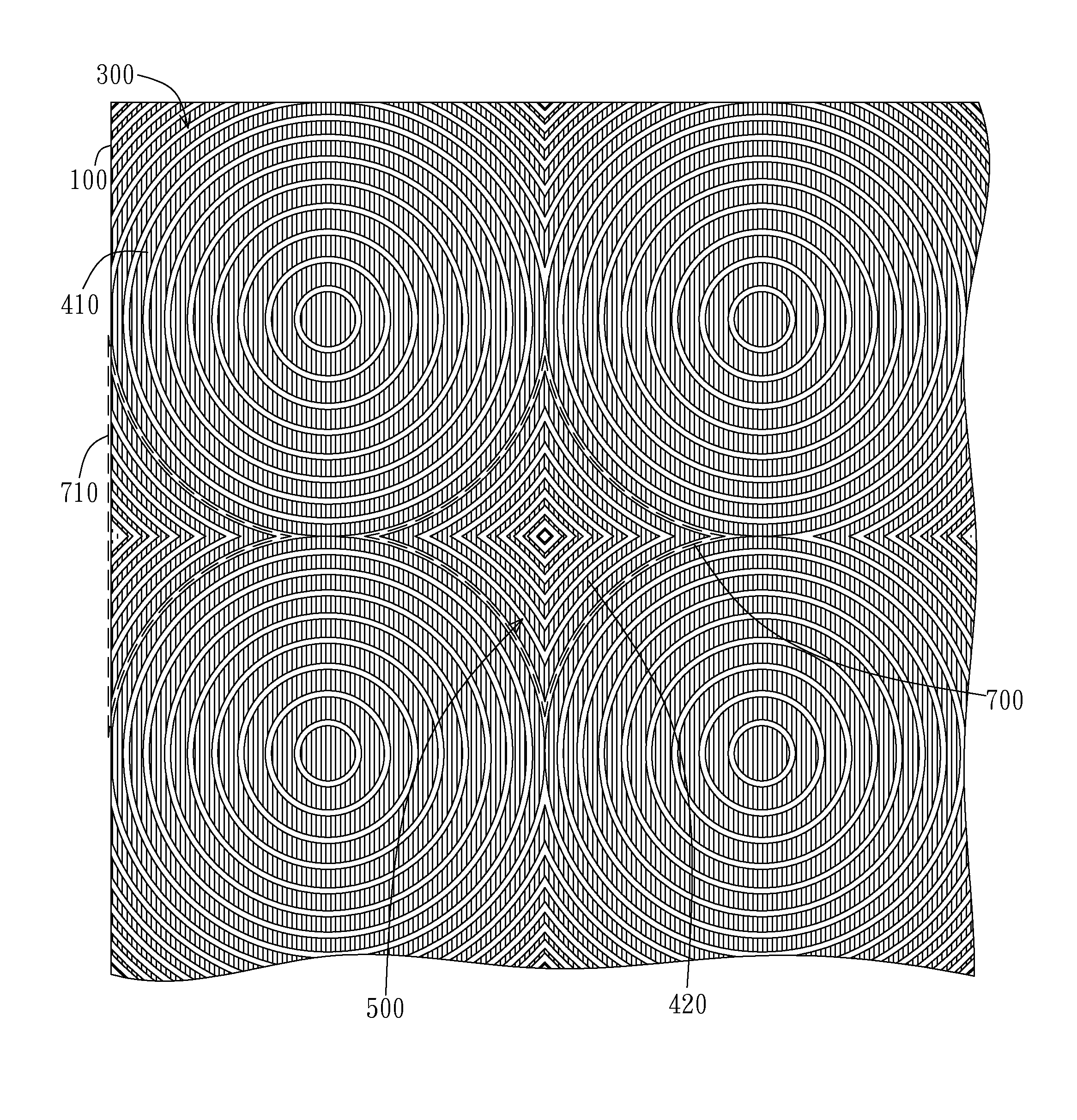
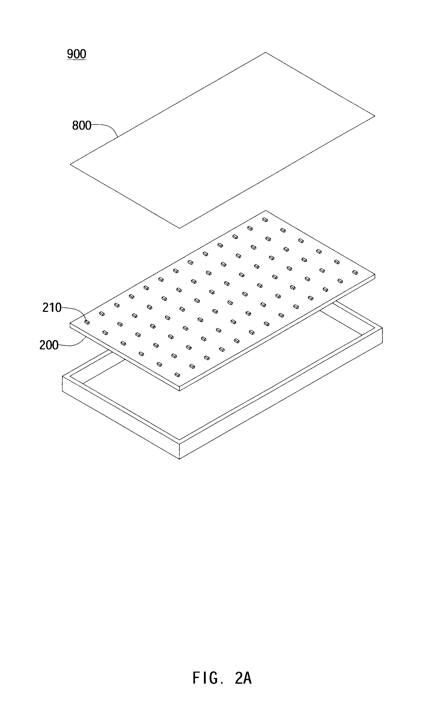
[0023]As the exploded view of the lighting module of the present invention shown in FIG. 2A, in a preferred embodiment, the diffusion plate 800 of the present invention is for use with the lighting module 900. More particularly, the lighting module 900 includes a light source module 200 and the diffusion plate 800. The light source module 200 includes a plurality of light sources 210, wherein the light source includes a light-emitting diode (LED). As the side view of one embodiment of the present invention shown in FIG. 2B, the diffusion plate 800 of the present invention includes a substrate 100 and a plurality of partial reflecting units 400 disposed on the surface of the substrate 100. Though the partial reflecting units 400 are disposed on the lower surface of the substrate 100 in the embodiment shown in FIG. 2B, the partial reflecting units 400 can also be disposed on the upper surface of the substrate 100 in other embodiments. When the light 600 emitted from the light source 2...


PUM


Abstract

A diffusion plate for use with a lighting module is provided. The diffusion plate includes a substrate, a plurality of circular diffusion structures, and at least one star diffusion structure. The circular diffusion structures are disposed on one face of the substrate in array. Each circular diffusion structure includes a plurality of first partial reflecting units. The first partial reflecting units are disposed on the substrate in circular distribution. The outer arcs of adjacent circular diffusion structures together form a star region. The at least one star diffusion structure includes a plurality of second partial reflecting units. The second partial reflecting units are disposed in the star region on the face of the substrate, wherein the second partial reflecting units are distributed in star distribution.

Description

BACKGROUND OF THE INVENTION[0001]1. Field of the Invention[0002]This invention generally relates to a diffusion plate. More particularly, this invention relates to a diffusion plate for use with a lighting module of a liquid crystal display.[0003]2. Description of the Prior Art[0004]Recently, liquid crystal displays are widely used in many display devices such as televisions, computers, laptops, monitors, cell phones, digital cameras, etc. A backlight module provides the liquid crystal display with a uniform light of sufficient brightness, so that the liquid crystal display can display images normally.[0005]As shown in FIG. 1, a conventional direct lighting-type backlight module 90 includes a light source module 200 and an optical film set 80. The optical film set 80 is a double-layer structure including a first diffusion plate 81 and a second diffusion plate 82, wherein micro-structures are respectively printed on one face of each of the first diffusion plate 81 and the second diff...

Claims


Application Information

Patent Timeline
Patent Type & Authority Patents(United States)
IPC IPC(8): F21V5/00
CPCG02B5/0215
Inventor CHANG, WEI-TIENTSAI, SHAU-YU
Owner AU OPTRONICS CORP
Why Eureka
Try Eureka