Safety spur

a safety spur and spur technology, applied in the field of safety spurs, can solve the problems of increasing the chance that the rider is thrown from the horse, his foot gets caught in the stirrup, and the rider's leg is tipped, so as to reduce the risk of falling off the horse and reduce the seriousness of the acciden

Active Publication Date: 2016-09-20
PHILLIPS KATHY
View PDF14 Cites 0 Cited by
  • Summary
  • Abstract
  • Description
  • Claims
  • Application Information

AI Technical Summary

Benefits of technology

[0011]Riders can get thrown from their horses when their heels get above their toes. Putting the heels above the toes pushes the bottom of the stirrup to backwards and raises the rider's center of gravity. It also pushes the feet deeper into the stirrup increasing the chance that the rider will be thrown from the horse and that his foot will get caught in the stirrup. Raising the heels above the toes also causes the rider's leg to tilt. The present invention provides for a sensor in a spur, which the rider wears, to detect when a rider tilts his leg by placing his heels higher than his toes. When the rider tilts his leg by placing his heels higher than his toes, the sensor senses the tilt of his leg and a radio transmitter in the spur transmits a warning to a radio receiver carried by the rider. In response to the warning the rider can adjust his feet in the stirrup and therefore be less likely to fall off the horse, or be thrown from the horse. When the rider adjusts his feet he will pull them back so that they are not as deep in the stirrup and thus the rider is less likely to have a foot stuck in a stirrup if he is thrown from the horse. Thus, the device helps to avoid the accident of getting thrown off the horse and lessens the seriousness of the accident if the rider is thrown.

Problems solved by technology

It also pushes the feet deeper into the stirrup increasing the chance that the rider will be thrown from the horse and that his foot will get caught in the stirrup.
Raising the heels above the toes also causes the rider's leg to tilt.

Method used


Image

  • Safety spur
  • Safety spur
  • Safety spur

Examples


example i

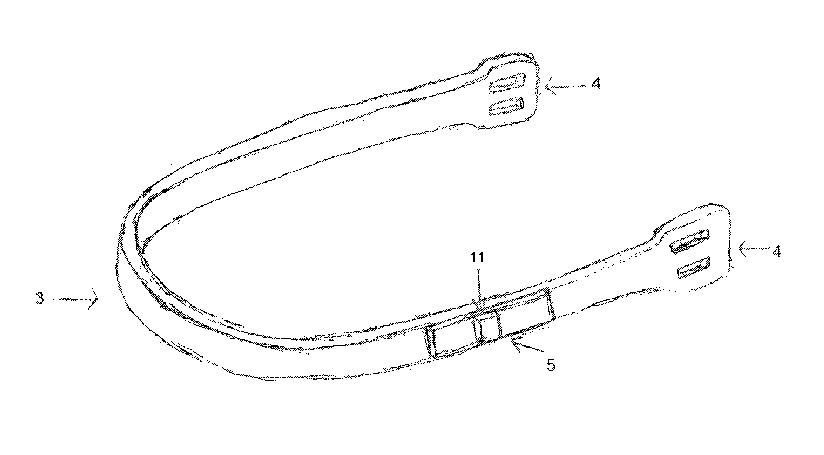
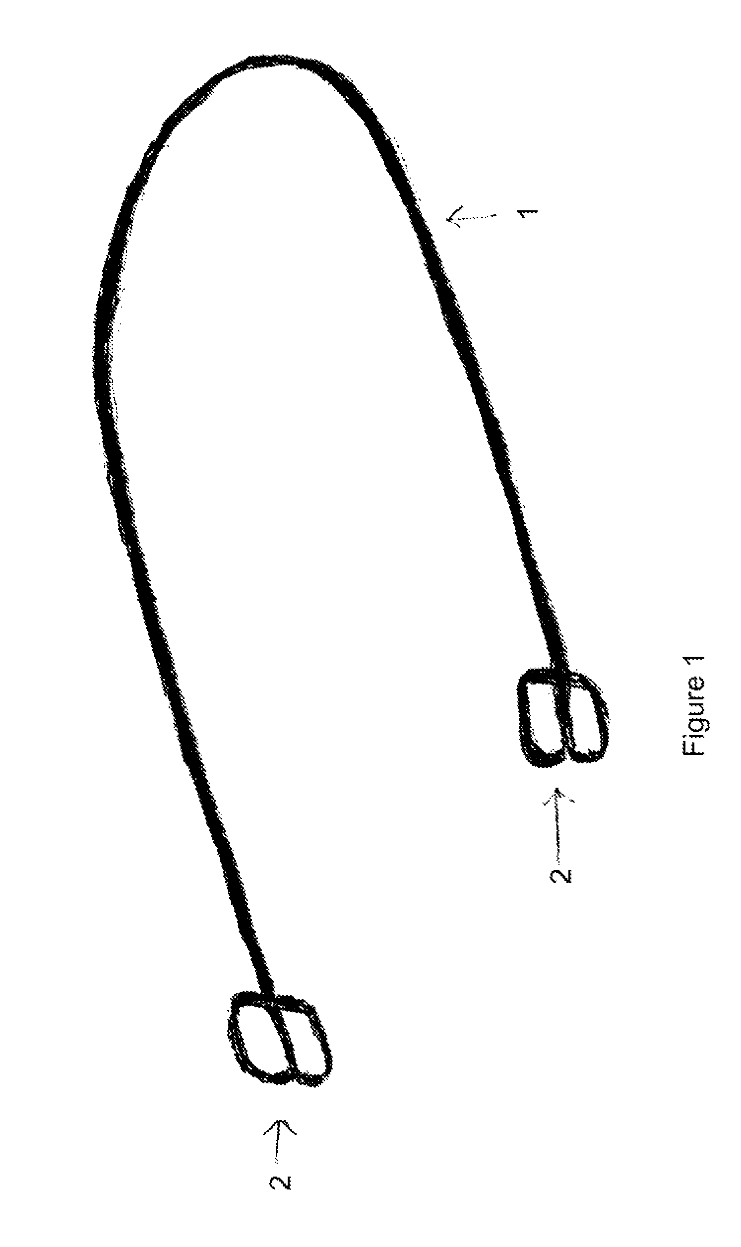
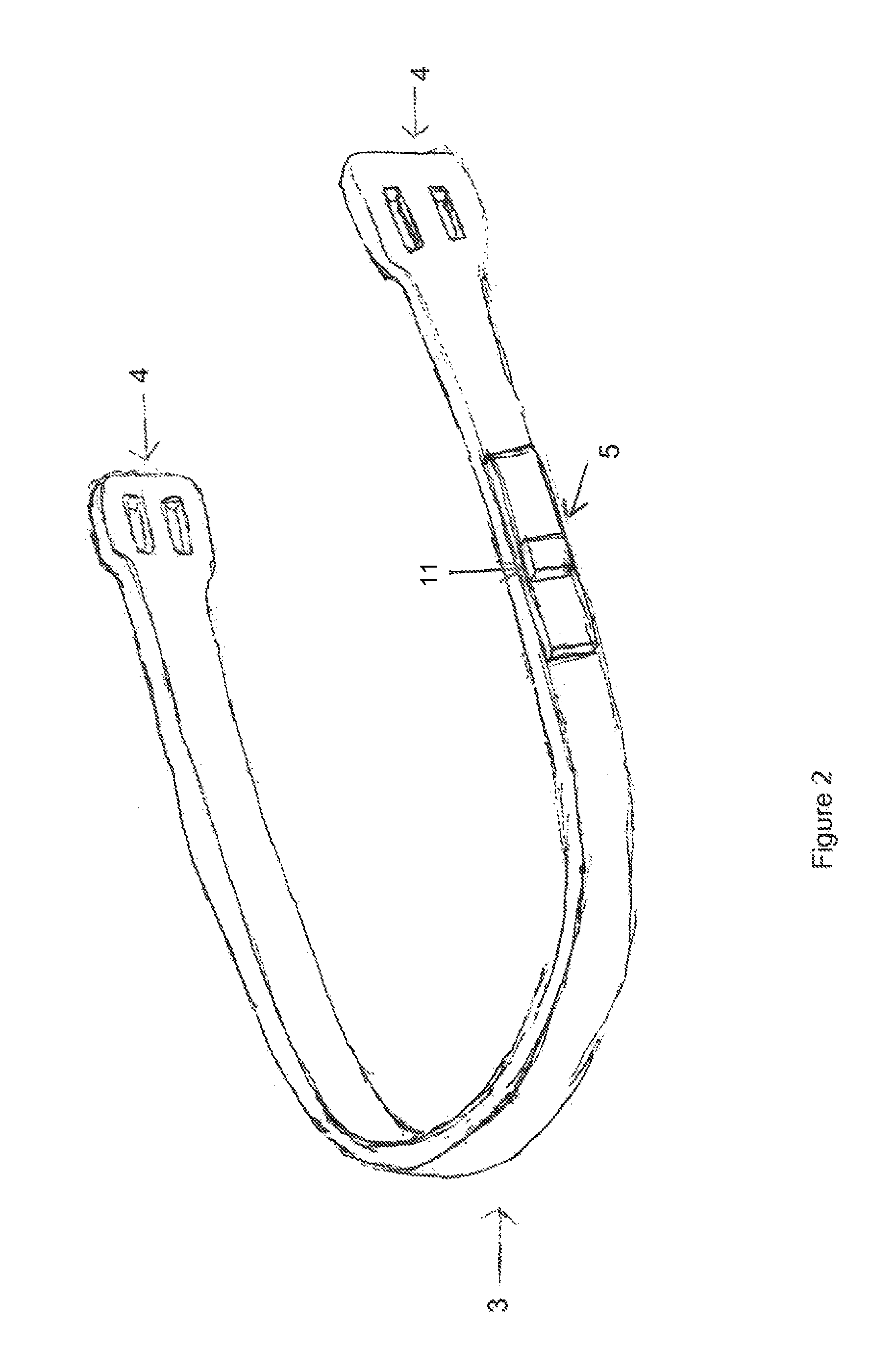
[0024]A spur 10 inches long from end to end was built. The body of the spur was made from an Alumilite polyurethane resin. The reinforcing structure was a 17 gauge wire that was approximately 14 inches long. The reinforcing wire was molded into a square spur strap buckle at each end. The spur band was approximately 1½″ wide. The spur contained a tilt sensor, which detects the angle of the rider's foot. The spur had a Linx Technologies transmitter operating at 433 megahertz, and a 12 volt battery. The round 17 gauge wire, the tilt sensor, the battery, and the transmitter were encased within the body of the spur. The battery in the spur may be accessed by removing a cover which is attached to the spur. The receiver and electronic audible indicator were contained within a plastic box. The plastic box was approximately 3×3×1½ inches in dimension. The box had a metal plastic clip which could be clipped to the rider's clothing. Within the receiver box there was a 9 volt battery which powe...


PUM


Abstract

This invention provides a safety spur which provides the rider a warning of a potentially dangerous foot position while riding a horse. The spur has a tilt sensor, a radio transmitter, and a radio receiver. Optionally, a 3 axis gyroscope may be used in place of a tilt sensor.

Description

CROSS REFERENCE TO RELATED APPLICATIONS[0001]This application asserts priority from provisional application 61 / 760,721, filed on Feb. 5, 2013, which is incorporated herein by reference.FIELD OF THE INVENTION[0002]This invention provides a safety spur which provides the rider a warning of a potentially dangerous foot position while riding a horse. This allows the rider to adopt a correct foot position and thereby avoid an accident.BACKGROUND OF THE INVENTION[0003]It is well known that riders, especially inexperienced riders can be unexpectedly thrown from their horse. Being thrown from a horse can often cause severe injury which can be made much worse if the stirrup catches the rider's foot. The rider can often be dragged a considerable distance behind the horse until the horse can be brought to a stop. The importance of this problem is indicated by the number of devices have been suggested which release the riders foot from the stirrup when the rider inadvertently dismounts from the...

Claims


Application Information

Patent Timeline
Patent Type & Authority Patents(United States)
IPC IPC(8): A43C17/00A43B3/00A63B71/06
CPCA43C17/00A43B3/0005A63B2071/0655A63B2220/18A63B2220/80A63B2244/24A43B3/34A43C17/02G08B21/18
Inventor PHILLIPS, KATHY
Owner PHILLIPS KATHY
Why Eureka
Try Eureka