
Foot peg assembly for A saddle-type vehicle

a technology of foot pegs and saddles, which is applied in the field of saddle vehicles, can solve the problems of hindering or even completely overcoming the ability, affecting the stability of the race course, and the soot of the race course is typically agitated and churning, and a satisfactory solution has yet to be developed

Active Publication Date: 2017-01-10
CRG RACING LLC
View PDF17 Cites 5 Cited by
  • Summary
  • Abstract
  • Description
  • Claims
  • Application Information

AI Technical Summary

Benefits of technology

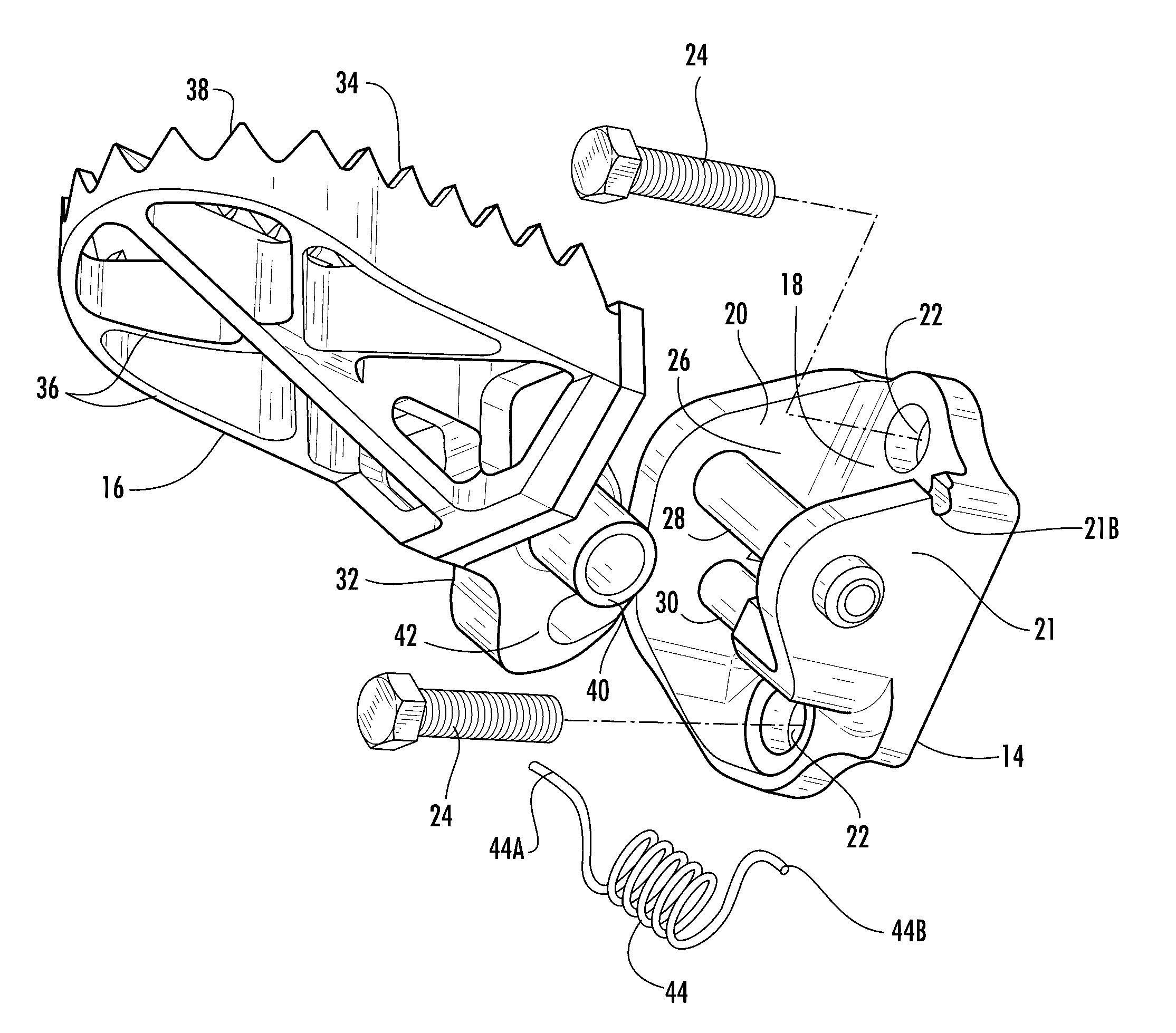
The patent proposes a foot peg assembly for saddle-type vehicles that is designed to keep out mud, dirt, and debris. The assembly includes a mounting bracket and a foot peg that is supported by the bracket and can pivot. The base of the foot peg has a step that serves as a surface for the rider's foot, and the base is attached to the bracket in a way that keeps the two close to each other. This prevents debris from getting in between the bracket and the step when the vehicle travels over uneven ground. The bracket may also have a mounting enclosure with a support rod and a guide rod extending through it between its walls, and the base may have a hub portion and a guard portion that move together as the foot peg moves. This configuration helps to keep debris out of the bracket. Overall, the foot peg assembly provides a better protection for the rider's foot and ensures a smoother ride on uneven ground.

Problems solved by technology

During a motocross race, the soil of the race course typically becomes agitated and churned as competitors operate their motorcycles at high speeds and take turns at extreme angles.
Unfortunately, however, mud, dirt and other debris can be thrown into the pivot mounting locations for the foot pegs which may hinder or even completely overcome the ability of the foot pegs to spring back into proper operating position.
While this problem has been known for some time, a satisfactory solution has yet to be developed.
Such deflectors may partially mitigate but are unable to prevent debris from entering the mounting locations for the foot pegs, so at best deflectors only somewhat delay the effects of debris.

Method used


Image

  • Foot peg assembly for A saddle-type vehicle
  • Foot peg assembly for A saddle-type vehicle
  • Foot peg assembly for A saddle-type vehicle

Examples


Embodiment Construction

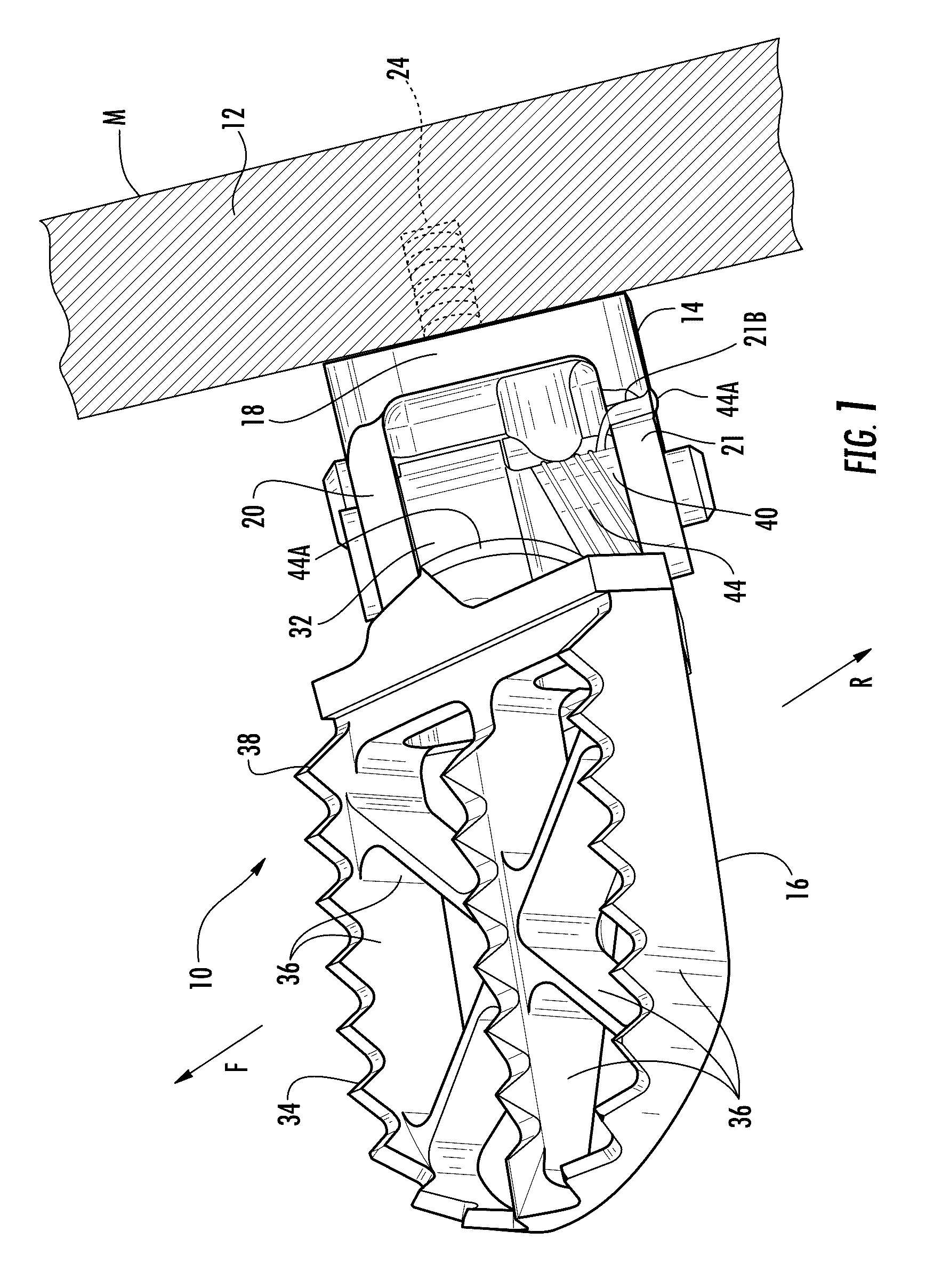
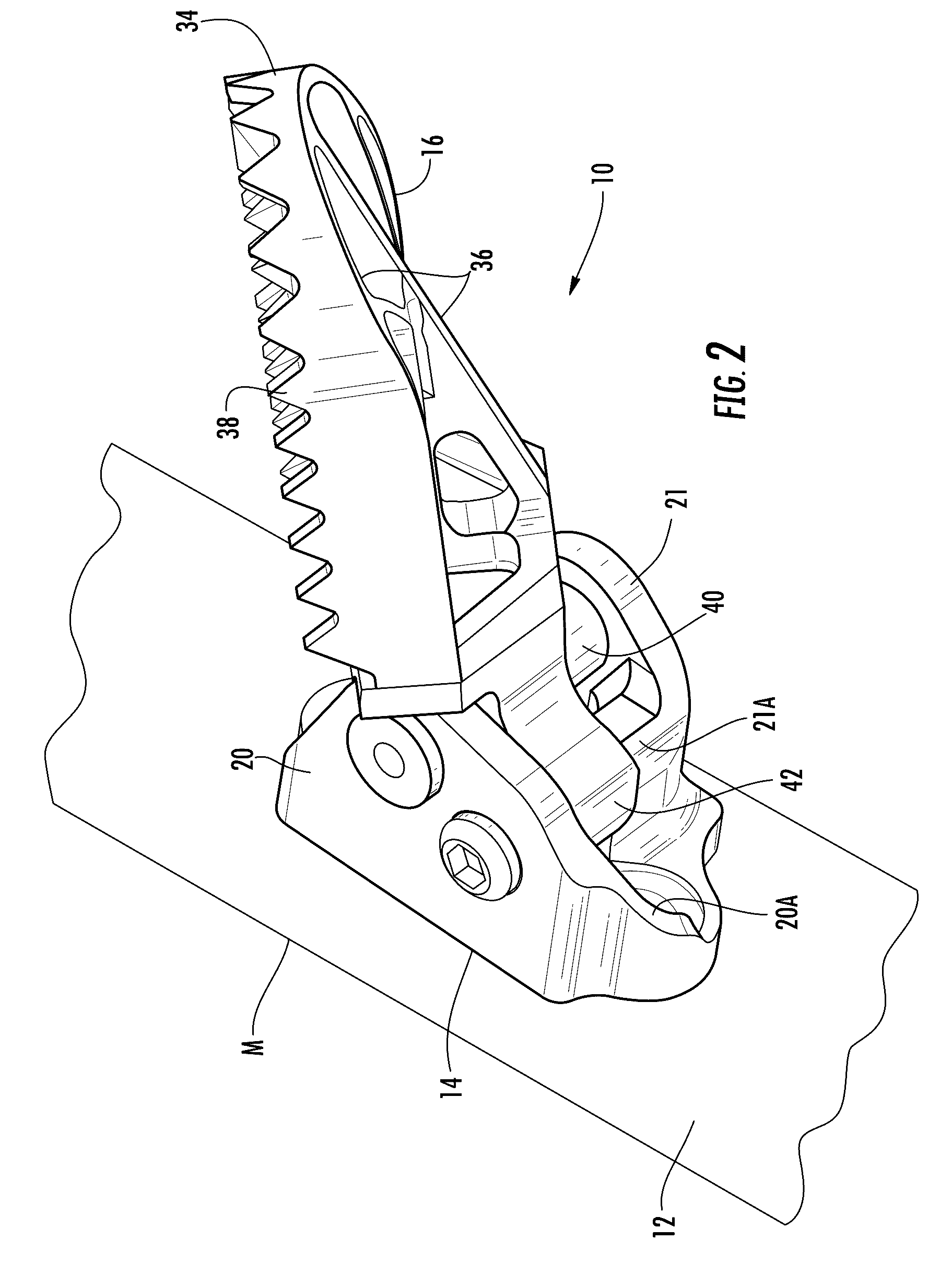
[0022]Referring now to the accompanying drawings and initially to FIGS. 1 and 2, a representative embodiment of a foot peg assembly in accordance with the present invention is indicated generally at 10 as mounted on the frame 12 of an off-road type motorcycle M. The forwardly facing direction of the frame 12 toward the front motorcycle wheel is indicated at F and the rearwardly facing direction of the frame toward the rear motorcycle wheel is indicated at R. The motorcycle M may be of any conventional construction, the various components and configuration of which are commonly known and understood and therefore are not otherwise shown or indicated.

[0023]The foot peg assembly 10 basically comprises two main components, a mounting bracket 14 affixed to the motorcycle frame 12 and a foot peg 16 supported pivotably on the mounting bracket 14. In the drawings of FIGS. 1 and 2, only a single foot peg assembly 10 is shown, but as will be readily understood by those knowledgeable and skille...


PUM


Abstract

A foot peg assembly for a saddle-type vehicle for supporting a rider's foot while seated or standing on the vehicle comprises a mounting bracket for affixation to a frame portion of the vehicle, and a foot peg supported pivotably on the mounting bracket. The foot peg has a base and a step integral with the base extending outwardly therefrom. The base is attached pivotably to the mounting bracket for pivoting movement of the step relative to the mounting bracket. The base and the mounting bracket have mutually complementary configurations which maintain a close spacing therebetween through the range of pivoting movement of the step to substantially close the mounting bracket from entry of debris when the vehicle travels over unpaved ground surfaces.

Description

CROSS-REFERENCE TO RELATED APPLICATIONS[0001]This is a continuation-in-part of co-pending U.S. patent application Ser. No. 14 / 988,874, filed Jan. 6, 2016, entitled FOOT PEG ASSEMBLY FOR A SADDLE-TYPE VEHICLE.FIELD OF THE INVENTION[0002]The present invention relates generally to saddle-type vehicles, and more particularly to foot pegs provided on the frames of such vehicles for supporting a rider's feet while seated or standing on the vehicle.BACKGROUND OF THE INVENTION[0003]As used herein, saddle type vehicles are intended to mean and to encompass any unenclosed vehicle which supports a rider in a position straddling a frame-mounted seat, including for example but without limitation two-wheeled vehicles such as bicycles and motorcycles and three-wheeled or four-wheeled vehicles such as so-called ATVs (all terrain vehicles).[0004]Many such saddle-type vehicles are designed and intended for, and commonly used in, so-called off-road work, recreational and racing activities over unpaved...

Claims


Application Information

Patent Timeline
IPC IPC(8): B62J25/00
CPCB62J25/00B62J25/04
Inventor BLOOMER, SPENCER J.
Owner CRG RACING LLC
Learn More