Packaged sensor assembly

a sensor and assembly technology, applied in the field of packaged sensor assembly, can solve problems such as affecting the useful signal of the signal, and achieve the effect of reducing the cost of the signal

Active Publication Date: 2017-01-10
STMICROELECTRONICS SRL
View PDF8 Cites 2 Cited by
  • Summary
  • Abstract
  • Description
  • Claims
  • Application Information

AI Technical Summary

Benefits of technology

[0012]FIG. 1 is a cross-sectional view of a packaged sensor assembly according to one embodiment of the present disclosure;

Problems solved by technology

In fact, incident radiation causes parasitic currents and consequent voltage drops that may alter the useful signals.

Method used


Image

  • Packaged sensor assembly
  • Packaged sensor assembly
  • Packaged sensor assembly

Examples


Embodiment Construction

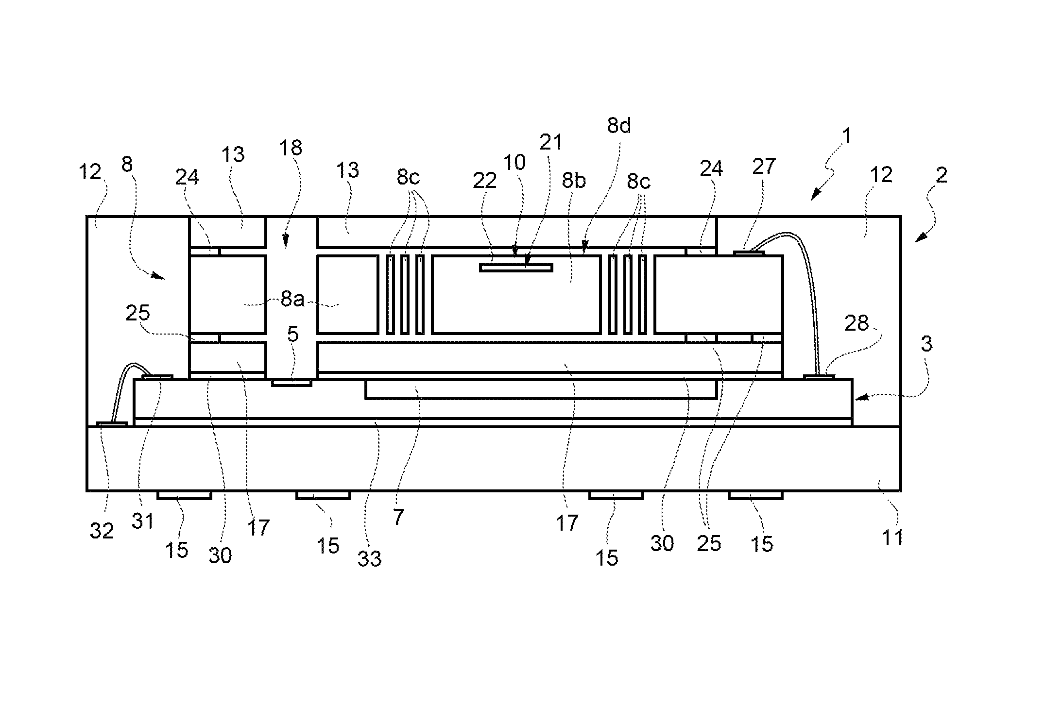
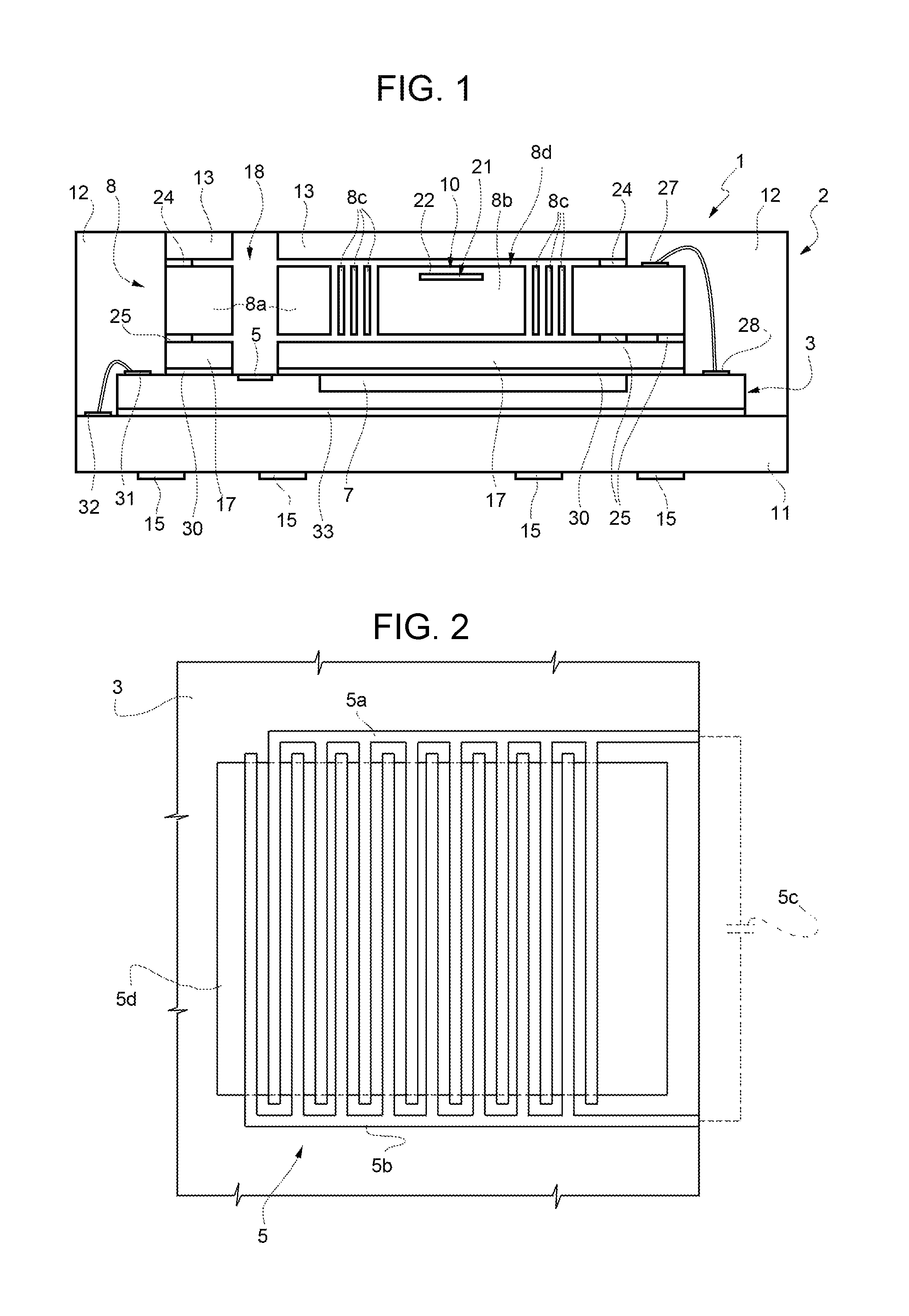
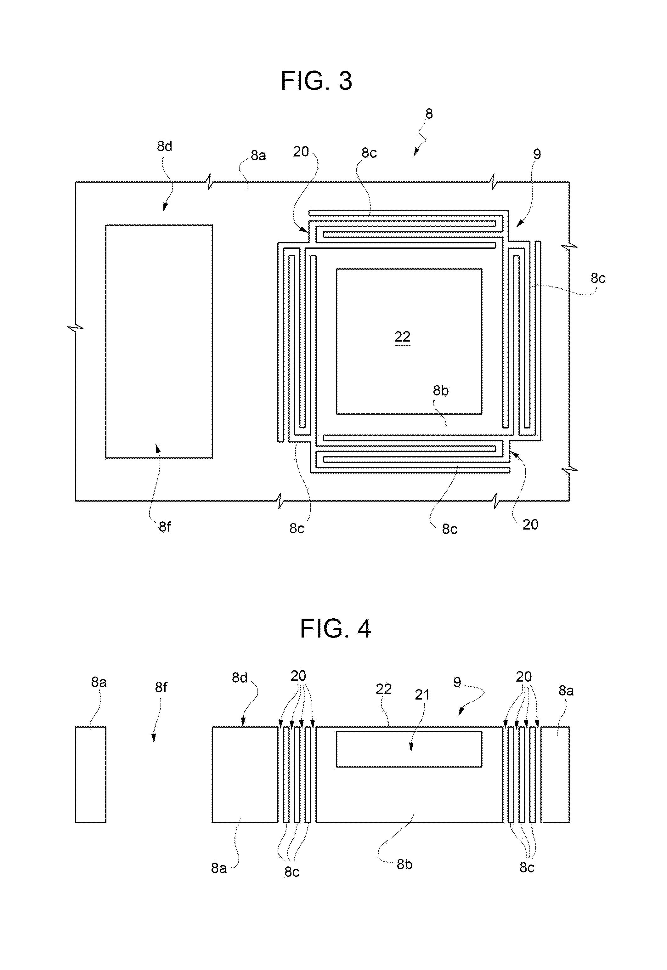
[0020]With reference to FIG. 1, a packaged sensor assembly according to one embodiment of the present disclosure is designated as a whole by 1 and comprises a packaging structure 2, a first chip 3, in which a humidity sensor 5 and a control circuit or ASIC 7 are integrated, and a second chip 8, in which an electromechanical transducer, such as a pressure sensor 10, is integrated.

[0021]The packaging structure 2 is of a molded type, for example of the land grid array (LGA) type, and comprises a substrate 11, a lateral structure 12, and a first cap 13. The substrate 11 is made, for example, of FR-4 and is provided with metal contact pads or lands 15 on an outer face. The lateral structure 12 may be made of resin and surrounds the first chip 3 and the second chip 8. In one embodiment, the lateral structure 12 is obtained by molding, for example using a technique of transfer molding, in particular film-assisted molding.

[0022]The first cap 13 defines a wall of the packaging structure 2 op...


PUM


Abstract

A packaged sensor assembly includes: a packaging structure, having at least one opening; a humidity sensor and a pressure sensor, which are housed inside the packaging structure and communicate fluidically with the outside through the opening, and a control circuit, operatively coupled to the humidity sensor and to the pressure sensor; wherein the humidity sensor and the control circuit are integrated in a first chip, and the pressure sensor is integrated in a second chip distinct from the first chip and bonded to the first chip.

Description

BACKGROUND[0001]Technical Field[0002]The present disclosure relates to a packaged sensor assembly.[0003]Description of the Related Art[0004]As is known, attention to the development and integration of microelectromechanical environmental sensors is progressively increasing as the use of portable electronic devices, such as smartphones and tablets or other so-called “wearable” electronic devices, increases. In particular, there is noted a specific interest to enclose a microelectromechanical pressure sensor and a microelectromechanical humidity sensor within a single packaging structure for electronic devices, together with a control circuit such as an application-specific integrated circuit (ASIC). The control circuit may serve for controlling operation of the sensors and as an interface for converting the electrical signals supplied by the sensors into data that may be used by further processing stages for performing various functions.[0005]A microelectromechanical pressure sensor ...

Claims


Application Information

Patent Timeline
Patent Type & Authority Patents(United States)
IPC IPC(8): B81B7/00
CPCB81B7/007B81B2201/0264B81B2201/0292B81B2207/094G01L19/0092G01N27/223H01L23/3121H01L2924/181H01L2224/32145H01L2224/48091H01L2224/73265B81B7/02H01L2924/00012H01L2924/00014B81B7/0058G08B7/02
Inventor BRUNO, GIUSEPPECONTI, SEBASTIANOCHIRICOSTA, MARIOVAIANA, MICHELEIPPOLITO, CALOGERO MARCOMAIORE, MARIOCASELLA, DANIELE
Owner STMICROELECTRONICS SRL
Why Eureka
Try Eureka