Eureka AIR delivers breakthrough ideas for toughest innovation challenges, trusted by R&D personnel around the world.

Method for the automated definition of color test values

a color test value and automatic definition technology, applied in the field of automatic definition of color test values, can solve the problem ofconsiderably shortening the color control process

Active Publication Date: 2017-01-31
HEIDELBERGER DRUCKMASCHINEN AG
View PDF5 Cites 2 Cited by
  • Summary
  • Abstract
  • Description
  • Claims
  • Application Information

AI Technical Summary

Benefits of technology

[0012]The method of the invention thus ensures that the major part of the settings for the certification process is predefined by the computer and that the process may be carried out by the operator without difficulty. As a result of the intentional predefined gradual over-inking or under-inking across multiple ink zones, e.g. 32 ink zones in the 70 format, a sufficiently wide gradation is achieved to ensure that a suitable dry-state target value is available. What are known as printing standards are basically only defined for CMYK printing. An additional advantage of the present invention is the addition of spot colors for package printers that produce the same product with different inking levels / standards for different countries. Depending on the selected color measurement strip, this is currently possible for up to ten colors.
[0013]Other features which are considered as characteristic for the invention are set forth in the appended claims.
[0014]Although the invention is illustrated and described herein as embodied in a automated definition of color test values, it is nevertheless not intended to be limited to the details shown, since various modifications and structural changes may be made therein without departing from the spirit of the invention and within the scope and range of equivalents of the claims.
[0015]The construction and method of operation of the invention, however, together with additional objects and advantages thereof will be best understood from the following description of specific embodiments when read in connection with the accompanying drawings.

Problems solved by technology

This considerably shortens the color control process.

Method used


Image

  • Method for the automated definition of color test values
  • Method for the automated definition of color test values

Examples


Embodiment Construction

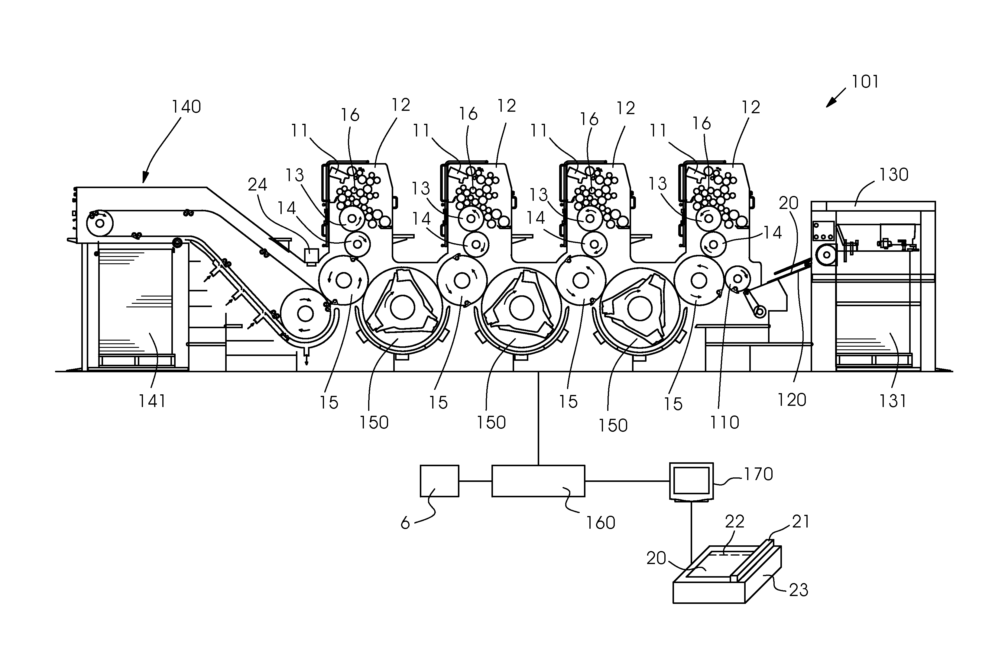
[0017]Referring now to the single FIGURE of the drawing in detail, the FIGURE illustrates an implementation of a method of the invention in a sheet-fed rotary lithographic offset printing press 101. It is to be understood that the method may be used in other lithographic offset printing presses. The sheet-fed printing press 101 in the FIGURE has four printing units 12 of essentially identical construction. Each printing unit 12 includes an inking unit 16 that is supplied with ink via an ink fountain 11 and evenly distributes the ink across the rollers in the inking unit 16 before applying it to a plate cylinder 13 carrying the printing form. The plate cylinder 13 in turn transfers the ink to the blanket cylinder 14. The blanket cylinder 14 and an impression cylinder 15 form a printing nip of the printing unit 12. Sheet-shaped printing substrates 20 are passed through the printing nip in each printing unit 12 to receive the respective color separation. In the printing press 101 in th...


PUM


Abstract

A method sets the inking in a printing press with multiple ink zones in an inking unit of a printing unit. The method includes: printing a test form onto a printing substrate with an intentional pre-defined color deviation from the intended target color; correcting the previously set ink setting and the defined set color deviation with regard to the respective target value in the wet condition of the printing substrate by a color measuring device; and taking color measurements of the dried printing substrate using the color measuring device. The measured color values established in the dry state and the original of the test form in a computer are compared. The ink setting that belongs to the ink zone with the smallest deviation from the intended target color is used as the target ink setting for the printing process.

Description

CROSS-REFERENCE TO RELATED APPLICATION[0001]This application claims the priority, under 35 U.S.C. §119, of German application DE 10 2013 012 299.6, filed Jul. 24, 2013; the prior application is herewith incorporated by reference in its entirety.BACKGROUND OF THE INVENTIONField of the Invention[0002]The present invention relates to a method for adjusting the ink settings in multiple steps in a printing press with multiple ink zones in an inking unit of a printing unit.[0003]In the production of print shop products, a major aspect is to reproduce the colors of the original, also referred to as the template, with as much fidelity as possible. This task is independent of the printing process that will be applied. However, in particular when rotary lithographic offset printing presses are used, quality demands are high especially in terms of color reproduction. Print shops need to meet these high quality requirements, some of them acquiring certificates in accordance with printing indust...

Claims


Application Information

Patent Timeline
Patent Type & Authority Patents(United States)
IPC IPC(8): B41F1/18B41F31/02B41F31/00B41F31/04B41F33/00
CPCB41F31/00B41F31/02B41F31/04B41F33/0027
Inventor DELANG, ULFBUCHER, HARALD
Owner HEIDELBERGER DRUCKMASCHINEN AG
Why Eureka
Eureka Blog
Learn More