Vehicle cargo compartment, system and vehicle

a cargo compartment and vehicle technology, applied in the field of vehicle cargo compartments, can solve problems such as taking responsibility off the loadmaster, and achieve the effect of easy and reliable monitoring

Active Publication Date: 2017-05-23
AIRBUS OPERATIONS GMBH
View PDF27 Cites 2 Cited by
  • Summary
  • Abstract
  • Description
  • Claims
  • Application Information

AI Technical Summary

Benefits of technology

[0009]Therefore, an object of the present invention is to provide a vehicle cargo compartment, where it can be monitored easily and reliably when the first latch claw is in the latched position.
[0012]In such a manner when the first latch claw is in the latched position the latch signal is generated and provided to the loadmaster, e.g., by means of a simple lamp or an optical display device indicating that either one or all latch claws in the cargo compartment are in the latched position. The loadmaster does not need to sight check each latch device himself but can rely on the latch signal provided to him e.g., on the display device. The process of monitoring the latch status after loading the cargo compartment becomes considerably faster, easier, and more reliable in such a way. Further, it takes responsibility off the loadmaster.
[0016]In a preferred embodiment the compartment housing comprises a housing floor and two opposite housing side walls at least partially surrounding a compartment interior space. The housing floor has an inner surface facing the compartment interior space. On said inner surface of the housing floor a roller track is provided extending in parallel to said housing side walls. The roller track comprises a track housing and a plurality of rollers rotatably mounted to said track housing. Each roller has an axis of rotation extending perpendicularly with respect to the direction of extension of the roller track. The rollers are adapted to engage a lower surface of a cargo unit received in said vehicle cargo compartment. The cargo units may easily be slid on the rollers through the vehicle cargo compartment. At least a share of said rollers are driven by a roller drive in order to transport a cargo unit inside of the vehicle cargo compartment.
[0018]Further, it is preferred that the first latch claw comprises a first claw arm and a first claw head connected to said first claw arm and adapted to engage a corresponding engagement section on a cargo unit received in the vehicle cargo compartment. The first claw arm is mounted to the latch housing pivotally by means of a first hinge. An axis of rotation of said first hinge being parallel to the axes of rotation of the rollers in the roller track. The first claw arm comprises an inner first arm section extending between the first hinge and the first claw head, and an outer first arm section extending away from the first hinge on that side of the first hinge opposite from the inner first arm section. In such a manner the first latch claw can be easily pivoted between latched and unlatched positions in the roller track.
[0019]In a preferred embodiment, the position sensor is mounted to the track housing underneath the latch device. In particular, it is preferred that the position sensor is directed upwards away from the housing floor, and that the target element is mounted to the inner first arm section of the first claw arm. In such a manner, the latched position of the first latch claw can be detected precisely and in a simple way.
[0020]Alternatively, it is preferred that the position sensor is directed in parallel to the axis of rotation of the first hinge, and that the target element is mounted to the outer first arm section of the first claw arm. In such a manner, the latched position of the first latch claw can be detected precisely and in a simple way.

Problems solved by technology

Further, it takes responsibility off the loadmaster.

Method used


Image

  • Vehicle cargo compartment, system and vehicle
  • Vehicle cargo compartment, system and vehicle
  • Vehicle cargo compartment, system and vehicle

Examples


Embodiment Construction

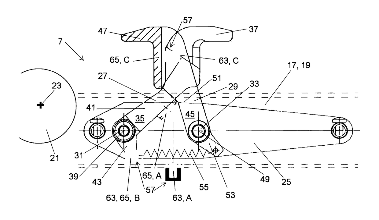
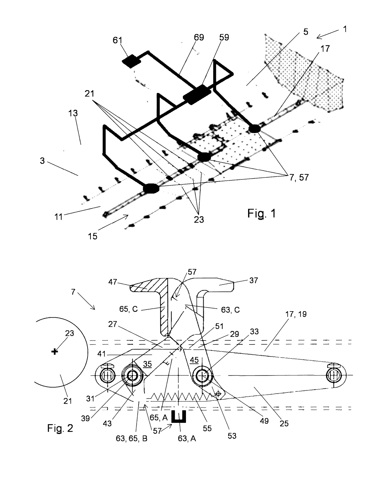
[0030]In FIG. 1 a preferred embodiment of the vehicle cargo compartment 1, in the present case an aircraft cargo compartment, according to the present invention is shown. Said vehicle cargo compartment 1 comprises a compartment housing 3 surrounding a compartment interior space 5, and a plurality of latch devices 7 mounted to said compartment housing 3 in order to latch a plurality of cargo units (not shown) received in said vehicle cargo compartment 1, in predetermined positions.

[0031]The compartment housing 3 comprises a housing floor 11 and two opposite housing side walls 13 extending upwards from said housing floor 11. The housing floor 11 has an inner surface 15 facing the compartment interior space 5. On said inner surface 15 of the housing floor 11 a roller track 17 is provided extending in parallel to the housing side walls 13 along the housing floor 11. Said roller track 17 comprises a track housing 19 and a plurality of rollers 21 rotatably mounted to said track housing 19...


PUM


Abstract

A vehicle cargo compartment, comprising a housing receivable in a vehicle, and at least one latch mounted to the housing for locking a cargo unit in a fixed position. The latch comprises a latch housing mounted to the housing, and at least a first latch claw moveably mounted to the latch housing moveable between a latched and an unlatched position. A latch sensor system comprises a position sensor and a target, the position sensor adapted to detect and generate a latch signal when the target is in the predetermined position. The vehicle cargo compartment can be monitored easily and reliably when the first latch claw is in the latched position due to the position sensor and the target being arranged and adapted such that the predetermined position of the target is detected and the latch signal is generated, when the first latch claw is in the latched position.

Description

CROSS-REFERENCES TO RELATED APPLICATIONS[0001]This application claims the benefit of the European patent application No. 14152741.6 filed on Jan. 27, 2014, the entire disclosures of which are incorporated herein by way of reference.BACKGROUND OF THE INVENTION[0002]The present invention relates to a vehicle cargo compartment, in particular an aircraft cargo compartment. Further aspects of the invention relate to a system of such a vehicle cargo compartment and at least one cargo unit received in said vehicle cargo compartment, as well as to a vehicle, in particular an aircraft, comprising such a vehicle cargo compartment.[0003]The vehicle cargo compartment comprises a compartment housing and at least one latch device. The compartment housing is adapted for being received in a vehicle, in particular in an aircraft fuselage. The latch device is mounted to said compartment housing and adapted for locking a cargo unit received in said vehicle cargo compartment, in a fixed and predetermin...

Claims


Application Information

Patent Timeline
Patent Type & Authority Patents(United States)
IPC IPC(8): B64D9/00B63B25/00B60P7/13
CPCB64D9/00B63B25/004B64D9/003B60P7/13
Inventor FISCHER, DENNISKAHLE, STEPHAN
Owner AIRBUS OPERATIONS GMBH
Why Eureka
Try Eureka