Projectile launcher

a projectile launcher and launcher technology, applied in the field of archery weapons, can solve the problems of limited shooting angles, frequent snagging of tree limbs and foliage, and exposed mechanism and bowstring cocking mechanism,

Active Publication Date: 2017-08-01
PRIOR MICHAEL W
View PDF13 Cites 38 Cited by
  • Summary
  • Abstract
  • Description
  • Claims
  • Application Information

AI Technical Summary

Benefits of technology

[0013]The projectile launcher includes a riser base, an elongate barrel assembly attached to the riser base, a crank mechanism attached to the back of the barrel assembly, a trigger assembly, and an internal bow assembly mounted to the riser base. The crank assembly includes a rotatable crank for selective reciprocation of a cocking carriage riding inside a rail system in the barrel assembly. The cocking carriage selectively engages a projectile nock carr

Problems solved by technology

Because of the large amount of force applied and mechanical energy stored and released, significant safety concerns exist due to the structure of a conventional crossbow.
The traditional crossbow, with its exposed mechanism and bowstring cocking mechanism, is not a compact design, which presents some ease of use concerns when applied to hunting applications as compared to a firearm/gun, and even the typical longbows and the like.
The large cross-sectional area created by the bow limbs being mounted transverse to the stock can result in frequent snagging with tree limbs and foliage when being transported in the field.
Mitigating the safety concerns described above often results in limited shooting angles when hunting in close proximity to trees due to the need for accommodating a “safe zone” around the bow limbs.
The use of external (to the bow) cocking mechanisms that must be attached to the bow each time it is cocked or uncocked and that rely upon the physical strength of the user to perform these actions can often result in cumbersome and strenuous manipulations of the bow and associated equipment in a hunting scenario due to limited space.
The use of the cross-mounted bo

Method used


Image

  • Projectile launcher
  • Projectile launcher
  • Projectile launcher

Examples


Embodiment Construction

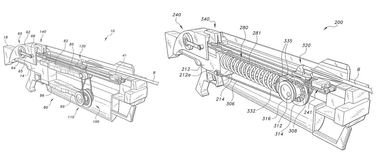
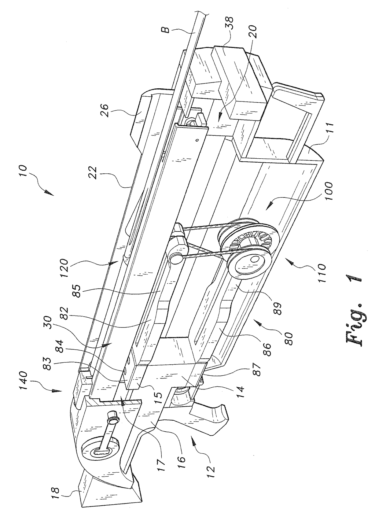
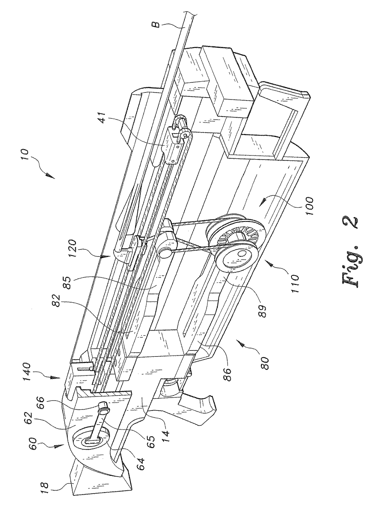
[0032]The projectile launcher, a first embodiment of which is generally referred to by the reference number 10, provides a well-balanced and enhanced safe-handling / firing archery-type weapon in a relatively compact, simple, and energy-efficient form. The term “projectile launcher,” as used herein, refers to a device capable of launching various types of elongate projectiles B, such as crossbow bolts, arrows, stakes, etc., that may be provided with either blunt or sharpened tips. As shown in FIGS. 1 and 2, the projectile launcher 10 includes a riser base 12 where the rest of the components of the projectile launcher 10 are mounted or attached. The riser base 12 is a substantially L-shaped block having a vertical short section 14 and an integral long section 16 extending transversely from an end of the short section 14. A portion of the long section 16 that meets with the short section 14 may be notched, forming a mounting ledge 15 for mounting one of the bow limbs, the details of whi...


PUM


Abstract

The projectile launcher includes a riser base, an elongate barrel assembly attached to the riser base, a crank mechanism attached to the back of the barrel assembly, a trigger assembly, and an internal bow assembly mounted to the riser base. The crank assembly includes a rotatable crank for selective reciprocation of a cocking carriage riding inside a rail system in the barrel assembly. The cocking carriage selectively engages a projectile nock carriage riding within the rail system to push the nock carriage into a cocked position. The internal bow assembly includes vertically spaced upper and lower resilient bow arms and a system of pulleys and cables interconnecting the bow arms and the nock carriage. Cocking to the nock carriage flexes the bow arms in preparation for placement and firing of a projectile. The working components of the projectile launcher are enclosed by a covering to protect the user.

Description

BACKGROUND OF THE INVENTION[0001]1. Field of the Invention[0002]The present invention relates to archery weapons, and particularly to a projectile launcher provided with covered, internalized bow elements and corresponding cocking mechanism for increased balance, safe handling, and minimized effort in operation.[0003]2. Description of the Related Art[0004]Crossbows have long been known in the art. The traditional design dates back to the 14th century or earlier, when very high powered crossbows were effective, especially against armored horsemen. A large medieval crossbow of circa 1500 A.D. might have a draw weight of 1200 pounds and a range of 450 yards. In modern times, crossbows rarely exceed 200 pounds draw weight. Modern crossbows now use sighting mechanisms of various sorts, advanced composite materials and metal alloys, wheel / pulley systems, etc., but otherwise are little changed, except in style and construction materials. Draw weights are dramatically lower, which are tailo...

Claims


Application Information

Patent Timeline
IPC IPC(8): F41B7/04F41B5/12F41B3/00F41B7/00F41B5/00
CPCF41B5/0094F41B7/003F41B3/005F41B5/12F41B5/123
Inventor PRIOR, MICHAEL W.
Owner PRIOR MICHAEL W
Why Eureka
Try Eureka