
Exhaust gas purification system for engine
a technology of exhaust gas purification system and engine, which is applied in the direction of machines/engines, electrical control, separation processes, etc., can solve the problems of engine output reduction, engine output reduction, damage to dpf, etc., and achieve accurate estimation of the accumulation state of pm
- Summary
- Abstract
- Description
- Claims
- Application Information
AI Technical Summary
Benefits of technology
Problems solved by technology
Method used
Image

Examples
first embodiment
(First Embodiment)
[0071]A behavior of the PM accumulation state estimation part 52 configured as above will be described with reference to the flowcharts shown in FIG. 4 to FIG. 6.
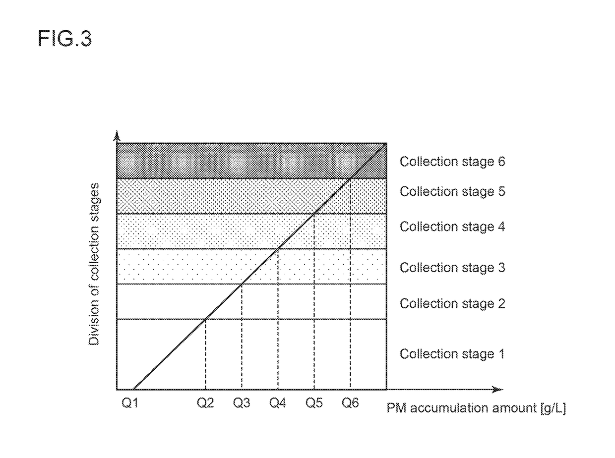
[0072]First, as illustrated in FIG. 4, in step S11, a current collection stage is determined by the above-described current stage determination part 52a. The current collection stage in step S11 is a collection stage which has been determined in the preceding cycle in the flowchart illustrated in FIG. 2 and is stored in the ECU 50.
[0073]Then, in step S12, detection determination is performed for the sensors by the above-described defect detection part 52d. That is, as illustrated in FIG. 6, whether a defect determination condition is satisfied is judged in step S31. Such judgment is made according to whether, in a case where the signal output from the sensor is a voltage signal, for example, the magnitude of the voltage falls within a prescribed range. Similarly, in a case where the signal output from the ...
second embodiment
(Second Embodiment)
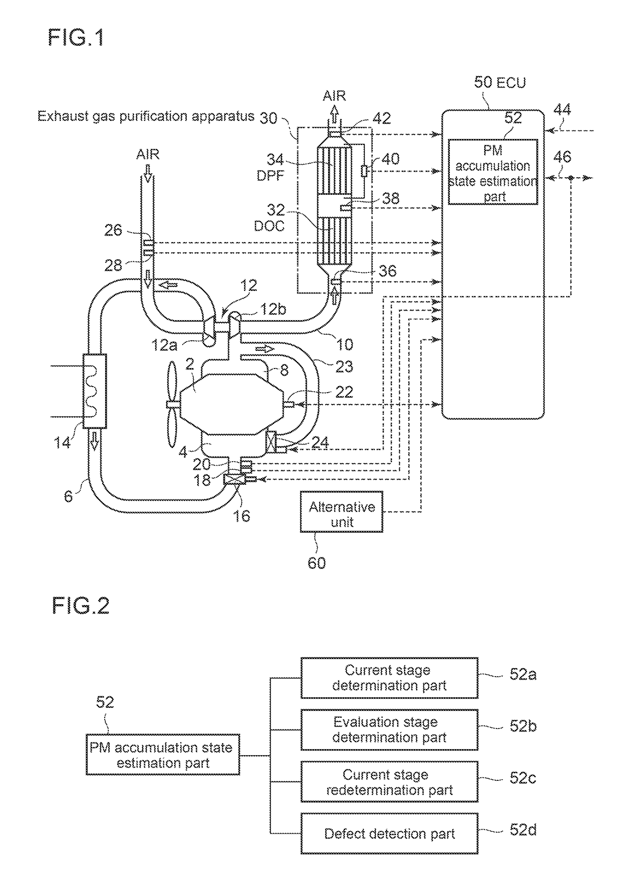
[0086]In the above embodiment, an example of a case where defects of two sensors i.e. the DPF inlet temperature sensor 38 and the DPF outlet temperature sensor 42 are detected is described. In this second embodiment, an example of a case where a defect of the DPF differential pressure sensor 40 is detected will be described with reference to FIG. 8 to FIG. 10. In this embodiment, the essential constitution is the same as in the above embodiment, and the same elements as those of the above embodiment are assigned with the same reference numerals as those of the above embodiment, and the same description thereof will be omitted.
[0087]As illustrated in FIG. 10, the DPF pressure difference, which is an output value of the DPF differential pressure sensor 40, is a base for calculation of the DPF corrected pressure difference, which is one of the four evaluation indices. Thus, in this embodiment, as illustrated in FIG. 8 and FIG. 9, in step S20, the current evaluation s...
third embodiment
(Third Embodiment)
[0090]The third embodiment of the present invention will be described with reference to FIG. 11 to FIG. 13. In this embodiment, the essential constitution is the same as in the above embodiment, and the same elements as those of the above embodiment are assigned with the same reference numerals as those of the above embodiment, and the same description thereof will be omitted.
[0091]In the above-described embodiments, when a defect of a sensor is detected by the defect detection part 52d, the current evaluation stage is newly redetermined by the current stage redetermination part 52c, and whether to move up the current evaluation stage to the next rank is determined by the evaluation stage determination part 52b, by using an evaluation index other than an evaluation index based on an output value of the sensor of which a defect is detected.
[0092]However, the present invention is not limited thereto, and as illustrated in FIG. 11 to FIG. 13, it may be configured so t...
PUM
| Property | Measurement | Unit |
|---|---|---|
| air flow rate | aaaaa | aaaaa |
| pressure | aaaaa | aaaaa |
| temperature | aaaaa | aaaaa |
Abstract
Description
Claims
Application Information