Shackle with self centering closure cross member

a cross member and self-centering technology, applied in the direction of shackles, load-engaging elements, vehicle components, etc., can solve the problems of many different sizes of washers and sleeves, difficult to obtain configuration, and the propensity of these small add-on parts to get lost when not in use,

Active Publication Date: 2017-08-08
TARRANT PATRICK M
View PDF17 Cites 10 Cited by
  • Summary
  • Abstract
  • Description
  • Claims
  • Application Information

AI Technical Summary

Benefits of technology

[0007]FIG. 1 is a side view of the shackle of the present invention with a partial cut away portion;

Problems solved by technology

However, this configuration is often difficult to obtain because most common shackles have a constant diameter closure cross member which allows the eye connection to the closure cross member to move along the member and naturally adjust to be at an angle less than 90 degrees to the shackle closure cross member centerline.
The draw back with both of these stop-gap measures is that both require many different sized washers and sleeves to be available because of the many different sized shackles employed in a typical hoisting job.
There is a propensity for these small type add-on parts to get lost when not in use and not be available when needed.
As such, the “valley” configuration cannot hold the same maximum load as the in-line configuration because of the additional stresses to which the valley configuration shackle is subject.

Method used


Image

  • Shackle with self centering closure cross member
  • Shackle with self centering closure cross member
  • Shackle with self centering closure cross member

Examples


Embodiment Construction

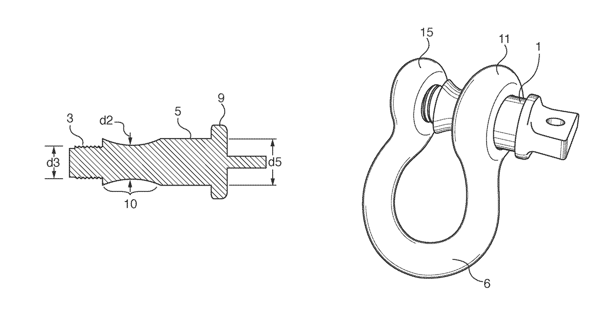
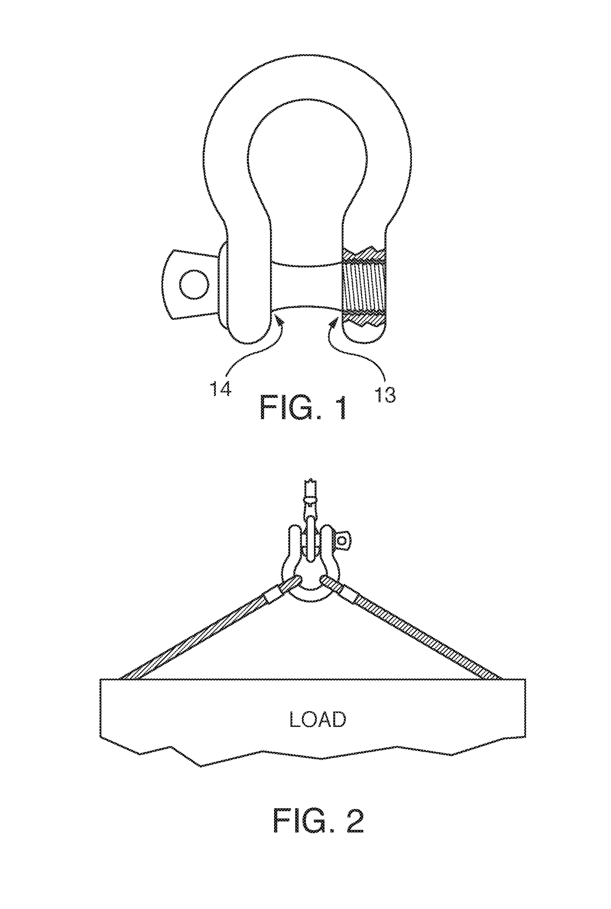
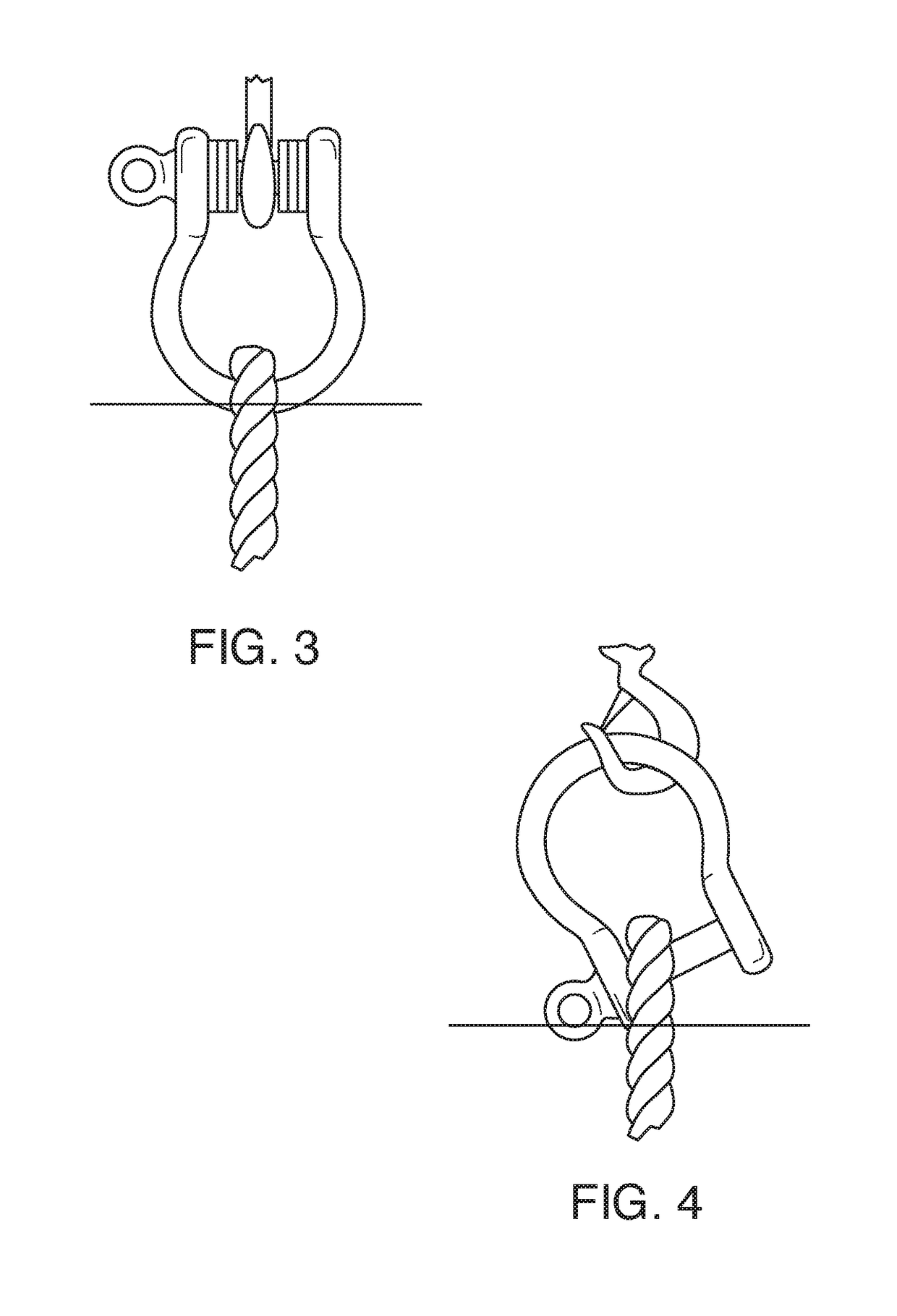
[0021]Shackles are used in rigging and come in a variety of sizes and load bearing capacities. Typically, a shackle has a retractable cross member (often called a closure cross member, bolt or pin) which fits through two lug holes equal in diameter located on both ends of the shackle loop (often called the shackle body or bail). FIG. 3 and FIG. 4.

[0022]Ropes or steel cables are usually rigged to a load and then connected to the main hook on a crane or other type hoist by means of a shackle. FIG. 2. Care should be taken to make certain that the connection to the closure member of the shackle is in the center of the closure member between the two lugs and at 90 degrees to the closure member pin centerline. FIG. 2 and FIG. 3. Side loading of the closure member should be avoided because the load bearing capacity of a shackle is compromised in this load configuration. FIG. 4. Instead, loading perpendicular to the cross member of the shackle and in the plane of the bow is preferred. FIG. ...


PUM


Abstract

A shackle with a closure cross member having a concave cross section is disclosed. The closure cross member is inserted into the lugs at the end of a bail of a shackle such that the concave cross section is disposed between the inner faces of the lugs on the bail. The concave cross section of the closure cross member works to center a wire or rope connected to the shackle closure cross member and ensure that the wire or rope is perpendicular to the centerline of the closure cross member. The concave cross section disposed between the inner faces of the lugs on the bail ensures that the wire or rope connecting a load to the shackle remains normal to the centerline of the closure cross member regardless of the movement or orientation of the load attached to the shackle.

Description

BACKGROUND OF INVENTION[0001]The present invention is directed to a shackle with a concave shaped diameter section in the center portion of the threaded cross member between the two lugs of the shackle. This feature facilitates the automatic centering of the connection (typically, the eye of a wire or rope) loaded on the cross member of the shackle.[0002]A shackle is comprised of a loop (referred to as the shackle body or bail)—often forged and often semi-circular in shape—with lugs located on each end. A cross member is fitted between these lugs and is typically screwed into the inside diameter of one of the lugs threaded to accept it. The cross member is also referred to as a closure pin, closure bolt or closure cross member. When using a shackle to lift a load with a crane or other hoisting device, the connection of the eye of the rope or wire on the shackle closure cross member should be at 90 degrees to the shackle closure cross member centerline. This lifting configuration pro...

Claims


Application Information

Patent Timeline
Patent Type & Authority Patents(United States)
IPC IPC(8): F16G15/04B66C1/66F16G15/06B60C27/08B66C1/10
CPCF16G15/06B66C1/66B66C1/10B60C27/08
Inventor TARRANT, PATRICK M
Owner TARRANT PATRICK M
Why Eureka
Try Eureka