Sheet manufacturing apparatus and sheet manufacturing method
a technology of sheet manufacturing and manufacturing method, which is applied in the direction of papermaking, damping devices, textiles and paper, etc., can solve the problems of increasing the size of the apparatus, taking time and effort to provide water treatment facilities maintenance, and requiring large amounts of water, and achieves high density. the effect of uniformity
- Summary
- Abstract
- Description
- Claims
- Application Information
AI Technical Summary
Benefits of technology
Problems solved by technology
Method used
Image
Examples
first embodiment
1. First Embodiment
1.1. Sheet Manufacturing Apparatus
1.1.1. Configuration
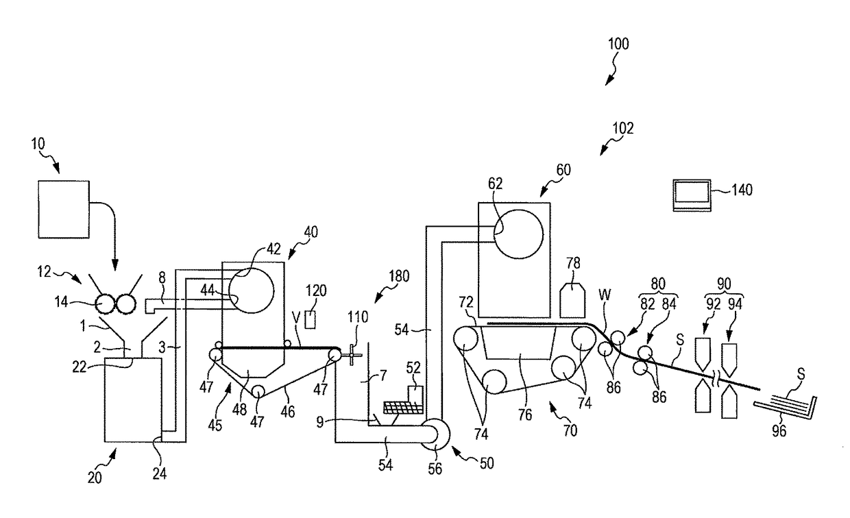
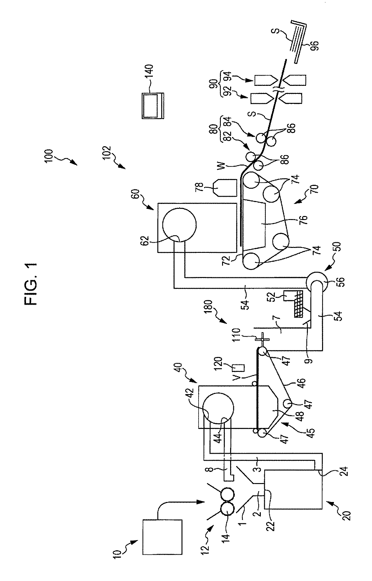
[0068]First, a sheet manufacturing apparatus according to a first embodiment will be described with reference to the drawings. FIG. 1 is a view schematically illustrating a sheet manufacturing apparatus 100 according to the first embodiment.
[0069]As illustrated in FIG. 1, the sheet manufacturing apparatus 100 includes a supply unit 10, a manufacturing unit 102, and a control unit 140. The manufacturing unit 102 manufactures a sheet. The manufacturing unit 102 has a crushing unit 12, a defibrating unit 20, a screening unit 40, a first web forming unit 45 (web forming unit), a mixing unit 50, a deposition unit 60, a second web forming unit 70, a sheet forming unit 80 (forming unit), and a cutting unit 90.
[0070]The supply unit 10 supplies a raw material to the crushing unit 12. The supply unit 10 is, for example, an automatic feeding unit for continuously feeding the raw material into the crushing unit 12. The raw...
second embodiment
2. Second Embodiment
2.1. Sheet Manufacturing Apparatus
[0140]Next, a sheet manufacturing apparatus according to a second embodiment will be described with reference to the drawings. FIG. 6 is a view schematically illustrating a sheet manufacturing apparatus 300 according to the second embodiment and is an enlarged view of a region including a rotary body 110. Hereinafter, in the sheet manufacturing apparatus 300, points different from the example of the above-described sheet manufacturing apparatus 100 will be described and description of the same points will be omitted.
[0141]As illustrated in FIG. 6, the sheet manufacturing apparatus 300 is different from the above-described sheet manufacturing apparatus 100 in that a peeling unit 310 is provided. The peeling unit 310 is a member for peeling a web V deposited on a mesh belt 46 from a mesh belt 46.
[0142]The peeling unit 310 has a stationary plate 312. Here, FIG. 7 is an enlarged view of a region including the stationary plate 312 of ...
first modification example
2.2.1. First Modification Example
[0147]Next, a sheet manufacturing apparatus according to a first modification example of the second embodiment will be described with reference to the drawings. FIG. 8 is a view schematically illustrating a sheet manufacturing apparatus 400 according to the first modification example of the second embodiment. Hereinafter, in the sheet manufacturing apparatus 400, points different from the examples of the above-described sheet manufacturing apparatuses 100 and 300 will be described and description of the same points will be omitted.
[0148]As illustrated in FIG. 8, the sheet manufacturing apparatus 400 is different from the above-described sheet manufacturing apparatus 300 in that a moisture-adjusting unit 478 for adjusting the moisture content of the web V is provided. The moisture-adjusting unit 478 can adjust an amount ratio of the web V and water by adding water or steam to the web V. In the illustrated example, a detection unit 120 is provided in a...
PUM
| Property | Measurement | Unit |
|---|---|---|
| speed | aaaaa | aaaaa |
| distance | aaaaa | aaaaa |
| distance | aaaaa | aaaaa |
Abstract
Description
Claims
Application Information
 - R&D
- Intellectual Property
- Life Sciences
- Materials
- Tech Scout
- Unparalleled Data Quality
- Higher Quality Content
- 60% Fewer Hallucinations
Browse by: Latest US Patents, China's latest patents, Technical Efficacy Thesaurus, Application Domain, Technology Topic, Popular Technical Reports.
© 2025 PatSnap. All rights reserved.Legal|Privacy policy|Modern Slavery Act Transparency Statement|Sitemap|About US| Contact US: help@patsnap.com


