Al technical title is built by PatSnap Al team. It summarizes the technical point description of the patent document.
a display system and image technology, applied in the field of display technology, can solve the problems of affecting the optimization affecting the chromaticity and saturation of the display panel, and the mixing efficiency of the rgb lights is lower, so as to achieve good chromaticity and saturation
Active Publication Date: 2017-10-03
TCL CHINA STAR OPTOELECTRONICS TECH CO LTD
View PDF6 Cites 0 Cited by
Summary
Abstract
Description
Claims
Application Information
AI Technical Summary
This helps you quickly interpret patents by identifying the three key elements:
Problems solved by technology
Method used
Benefits of technology
[0038]Compared with conventional technology, a method for image display and a display system adopting the method proposed by the present invention have a feature as follow: Grayscale values are transformed into corresponding brightness values at first; next, the data signal carrying the R, G, B, and W pixels obtains corresponding compensated brightness values after the brightness values are calculated; next, the brightness values which the data signal carrying the R, G, B, and W pixels corresponds to are transformed into grayscale values in the process of transforming the data signal carrying the R, G, and B pixels into the data signal carrying the R, G, B, and W pixels. By adopting the brightness values as the median of grayscale, it is possible to maintain as good chromaticity and saturation using the transformed grayscale values R′, G′, B′, and W′, as when the grayscale values R, G, and B are used.
Problems solved by technology
A conventional method for mixing the RGB lights has a lower rate of penetration and a lower mixing efficiency while having a higher power consumption of the conventional display panel, which hinders optimization of the display panel.
Using the obtained grayscale values R′, G′, B′, and W′, it is not possible to maintain as good chromaticity and saturation as when the original grayscale values R, G, and B are used.
Method used
Image
Click on the blue label to locate the original text in one second.
Reading with bidirectional positioning of images and text.
Examples
Embodiment Construction
[0040]For better understanding embodiments of the present invention, the following detailed description taken in conjunction with the accompanying drawings is provided. Apparently, the accompanying drawings are merely for some of the embodiments of the present invention. Any ordinarily skilled person in the technical field of the present invention could still obtain other accompanying drawings without use laborious invention based on the present accompanying drawings.
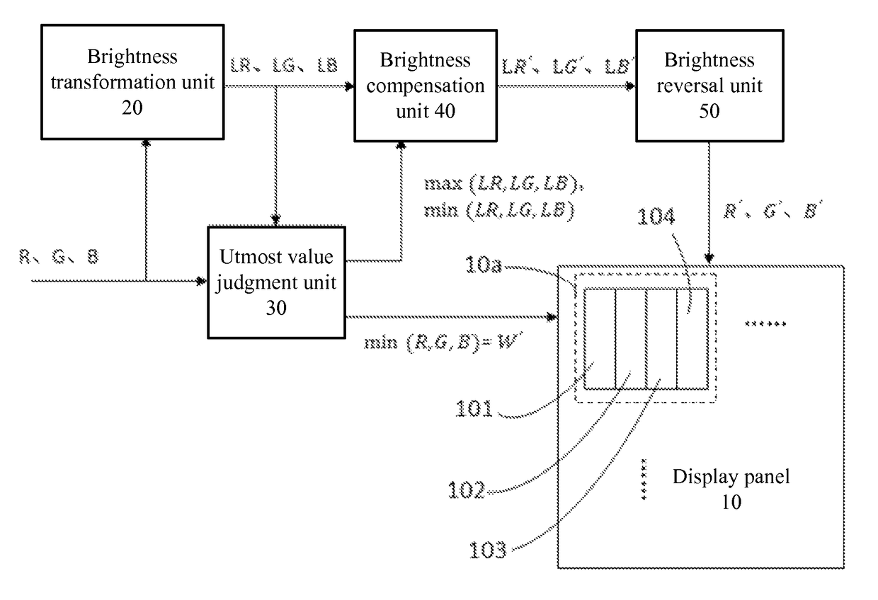
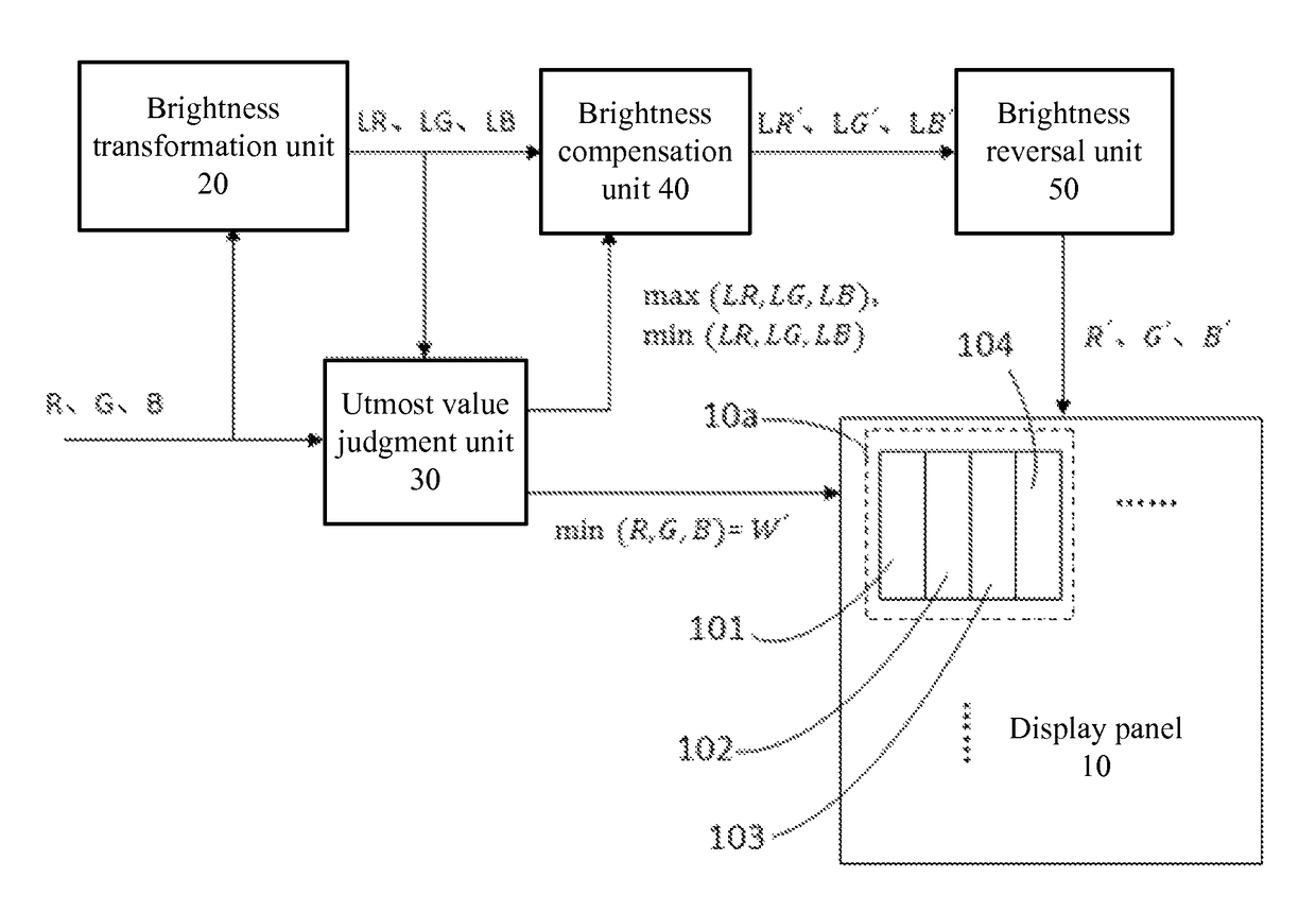
[0041]Please refer to FIG. 1. An image display system is proposed by an embodiment of the present invention. The system comprises a display panel 10, a brightness transformation unit 20, an utmost value judgment unit 30, a brightness compensation unit 40, and a brightness reversal unit 50.
[0042]The display panel 10 comprises a plurality of pixels 10a. Each of the plurality of pixels 10a comprises a red subpixel 101, a green subpixel 102, a blue subpixel 103, and a white subpixel 104. The display panel 10 may be an LCD p...
PUM
Abstract
A method for image display is provided. The method includes: providing a data signal of an image, and the data signal comprising grayscale values R, G, and B; obtaining brightness values LR, LG, and LB which the grayscale values R, G, and B correspond to; transforming the brightness values LR, LG, and LB into brightness values LR′, LG′, and LB′; obtaining grayscale values R′, G′, and B′ which the brightness values LR′, LG′, and LB′ correspond to; obtaining a minimum value among the grayscale values R, G, and B as a white grayscale value W′; and supplying the red subpixel, the green subpixel, the blue subpixel, and the white subpixel with the grayscale value R′, G′, B′, and white grayscale value W′, respectively so that the image can be shown on the display panel. The present invention also proposes a display system utilizing the method.
Description
BACKGROUND OF THE INVENTION[0001]1. Field of the Invention[0002]The present invention relates to the field of display technology, and more particularly, to a method for image display and a display system adopting the method.[0003]2. Description of the Prior Art[0004]Nowadays, a red (R) subpixel, a green (G) subpixel, and a blue (B) subpixel form a pixel for an image display device such as a liquid crystal display (LCD) panel and an organic light-emitting diode (OLED) panel. Any required colors can be successfully mixed and obtained to show colorful images by controlling the grayscale value of each of the subpixels. With the development of information technology (IT), demands for display panels with various features are increasing such as high rate of penetration, low power consumption, and high-quality imagery. A conventional method for mixing the RGB lights has a lower rate of penetration and a lower mixing efficiency while having a higher power consumption of the conventional disp...
Claims
Application Information
Patent Timeline
Application Date:The date an application was filed.
Publication Date:The date a patent or application was officially published.
First Publication Date:The earliest publication date of a patent with the same application number.
Issue Date:Publication date of the patent grant document.
PCT Entry Date:The Entry date of PCT National Phase.
Estimated Expiry Date:The statutory expiry date of a patent right according to the Patent Law, and it is the longest term of protection that the patent right can achieve without the termination of the patent right due to other reasons(Term extension factor has been taken into account ).
Invalid Date:Actual expiry date is based on effective date or publication date of legal transaction data of invalid patent.