Light emitting device with light transmissive member and method for manufacturing thereof

a technology of light transmitting device and light transmitting member, which is applied in the direction of semiconductor device, semiconductor/solid-state device details, electrical apparatus, etc., can solve the problems of poor durability of color conversion materials, difficult to obtain small and thin light emitting devices with good chromaticity and color reproducibility, etc., and achieves simple method and good color reproducibility

Active Publication Date: 2017-11-21
NICHIA CORP
View PDF39 Cites 1 Cited by
  • Summary
  • Abstract
  • Description
  • Claims
  • Application Information

AI Technical Summary

Benefits of technology

[0009]It is an object of the present invention to provide a light emitting device and method for manufacturing thereof, with which a light emitting element with a small and thin size can be obtained while desired chromaticity and good color reproducibility can be achieved by a simple method.
[0020]According to the present disclosure, it is possible to provide a light emitting device and method for manufacturing thereof, with which a light emitting device with small and thin size can be obtained while even better chromaticity and color reproducibility can be achieved by a simple method.

Problems solved by technology

However, in recent years, color conversion materials with poor durability are becoming more frequently used, and in this case, obtaining a small and thin light emitting device with good chromaticity and color reproducibility may be difficult.

Method used


Image

  • Light emitting device with light transmissive member and method for manufacturing thereof
  • Light emitting device with light transmissive member and method for manufacturing thereof
  • Light emitting device with light transmissive member and method for manufacturing thereof

Examples


embodiment 1

issive Member and Method for Manufacturing Thereof

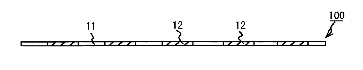
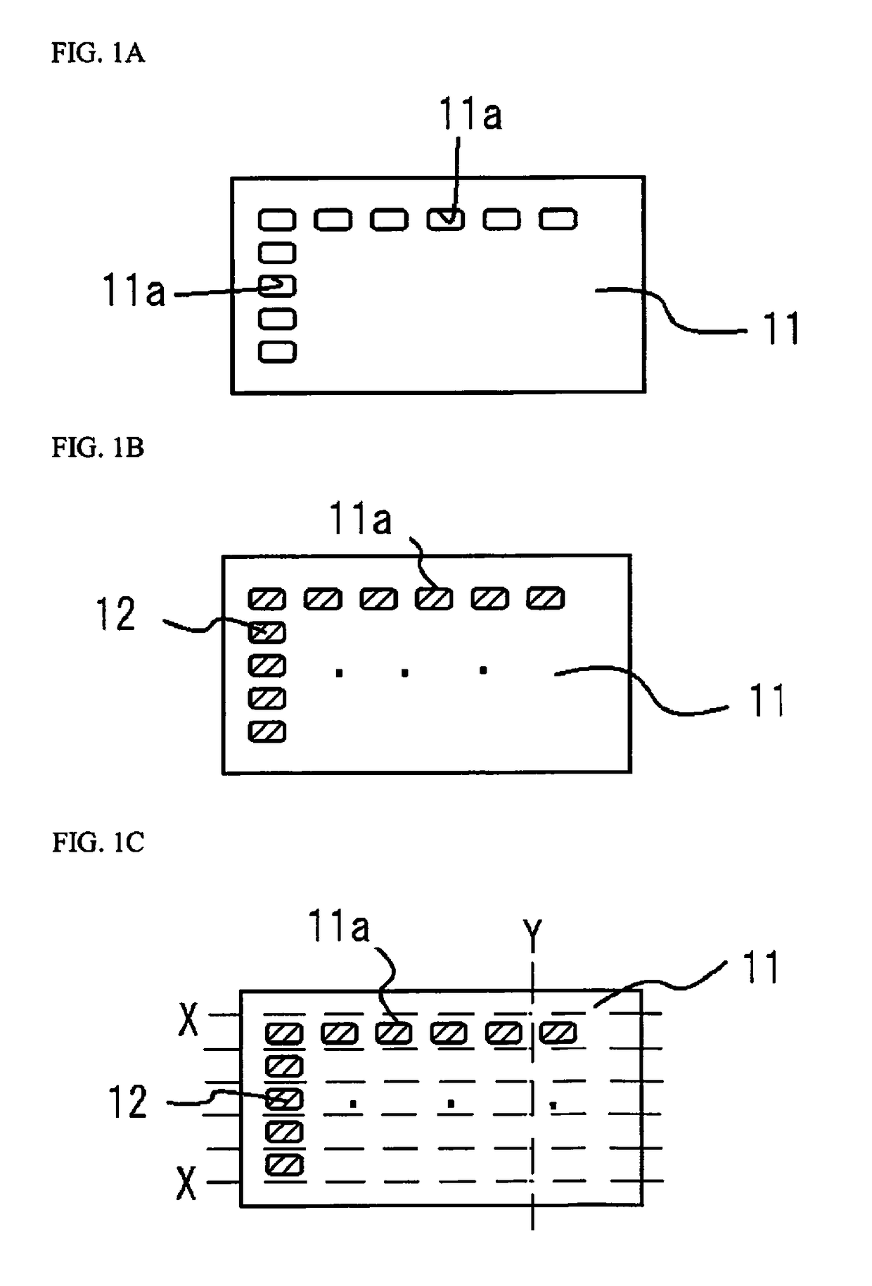
[0187]First, a light reflective sheet 11 is prepared as shown in FIG. 1A.

[0188]The light reflective sheet 11 is made of a silicone resin that contains 60 wt % TiO2, which is a light reflective substance, and is formed into a sheet with a thickness of 200 μm.

[0189]A plurality of substantially rectangular through-holes 11a that measure 1.1×0.2 mm are arranged in a row and column on this light reflective sheet 11.

[0190]Next, as shown in FIG. 1B, the through-holes 11a are filled by potting with a slurry obtained by mixing 18 wt % KSF phosphor with a particle size of about 20 μm, 26 wt % beta-SiAlON with a particle size of about 12 μm, and 56 wt % light-transmissive resin (silicone resin), and the mixture is cured. The curing of the light-transmissive resin is accomplished by heating at 150° C. for 240 minutes in an oven. This forms a color conversion material layer 12. This color conversion material layer 12 is substantially flush with t...

modification example 1

ber

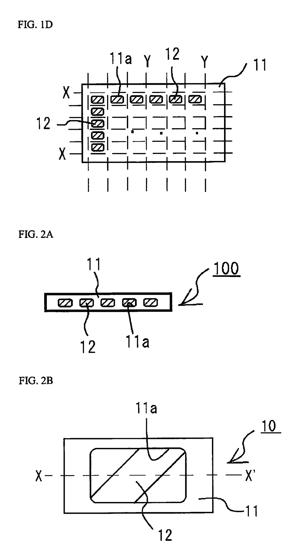
[0195]As shown in FIG. 9, instead of the light-transmissive member 100 shown in FIG. 2A, a plurality of color conversion material layers 12X may be arranged in a ring shape on a single light reflective sheet 11X.

modification example 2

ber

[0196]Instead of the light-transmissive member 10 shown in FIGS. 2B and 2C, color conversion material layers 12A to 12H and 12M may be concave and / or convex with respect to the upper surface and / or lower surface of the light reflective sheet 11, as with the light-transmissive members 1 OA to 10H and 10M shown in FIG. 8. In the case where the upper surface and / or lower surfaces of the color conversion material layer is concave with respect to the upper surface and / or lower surface of the light reflective sheet, light convergence or other such effects can be exhibited. Also, in the case where the upper surfaces and / or lower surfaces of the color conversion material layers are convex with respect to the upper surface and / or lower surface of the light reflective sheet, an adhesion the light emitting elements being used can be improved. Furthermore, in the case where the shape is convex with respect to the upper surface of the light reflective sheet, light extraction efficiency can be...


PUM

PropertyMeasurementUnit
light reflectivityaaaaaaaaaa

Abstract

A method of manufacturing a light emitting device includes: preparing a light-transmissive member including a light reflective sheet that has a through-hole, and a color conversion material layer that is composed of a light-transmissive resin containing a color conversion material and disposed in the through-hole, preparing a light emitting element, fixing the color conversion material layer to the light emitting element, covering a side surface of the light emitting element with a light-reflective member, and cutting the light-reflective member and light-reflective sheet.

Description

CROSS-REFERENCE TO RELATED APPLICATIONS[0001]This application claims priority to Japanese Patent Application No. 2014-201416 filed on Sep. 30, 2014. The entire disclosure of Japanese Patent Application No. 2014-201416 is hereby incorporated herein by reference.BACKGROUND[0002]1. Field of the Invention[0003]The present invention relates to a light emitting device and a method for manufacturing thereof.[0004]2. Description of Related Art[0005]As the quality of light emitting diodes has improved in recent years, they are used with various configurations in the field of general lighting, the field of automotive lighting, and so forth.[0006]For example, an effort to obtain smaller and thinner light emitting devices has been made.[0007]Also, chromaticity and color reproducibility of a light emitting device improved by using various kinds of color conversion materials in combination with a light emitting diode that has achieved high output, high brightness, and so forth (For example, JP 20...

Claims


Application Information

Patent Timeline
Patent Type & Authority Patents(United States)
IPC IPC(8): H01L23/00H01L33/50H01L33/48
CPCH01L24/97H01L33/505H01L33/486H01L2224/16225H01L2933/0041H01L2224/48091H01L2924/00014H01L33/508H01L33/54H01L33/60H01L33/56
Inventor TAMAKI, HIROTONAKABAYASHI, TAKUYA
Owner NICHIA CORP
Why Eureka
Try Eureka