Electrooptic device, driving circuit, and electronic device

a driving circuit and electronic device technology, applied in the field of electronic devices, can solve the problems of unsuitable human visual sense, inability to automatically control the backlight in consideration of contrast and color matching, and waste of power consumption, so as to reduce power consumption of the illuminating unit, improve display quality, and control the brightness of the display panel.

Inactive Publication Date: 2007-08-16
EPSON IMAGING DEVICES CORP
View PDF6 Cites 62 Cited by
  • Summary
  • Abstract
  • Description
  • Claims
  • Application Information

AI Technical Summary

Benefits of technology

[0032]Thus, the driving circuit is allowed to automatically control the light of the illuminating unit by the light control unit, thereby providing the optimum surface luminance suitable for humans' visual sense. Moreover, the display-mode switching unit switches the display panel between the transmission display mode and the reflection display mode accordin

Problems solved by technology

Nevertheless, illuminating units illuminate the liquid-crystal display panel at constant luminance all the time.
Moreover, illuminating units use the same constant-luminance light source as that for dark places even in very light places where the luminance of the reflected light is higher than that of transmitted light, causing wasteful power consumption.
This method has the problem that if the method is applied to a liquid crystal device having multicolo

Method used


Image

  • Electrooptic device, driving circuit, and electronic device
  • Electrooptic device, driving circuit, and electronic device
  • Electrooptic device, driving circuit, and electronic device

Examples


Embodiment Construction

[0048]Preferred embodiments of the invention will be described with reference to the drawings. The embodiments are applications of the invention to a liquid crystal device as an example of electrooptic devices.

Structure of Liquid Crystal Device

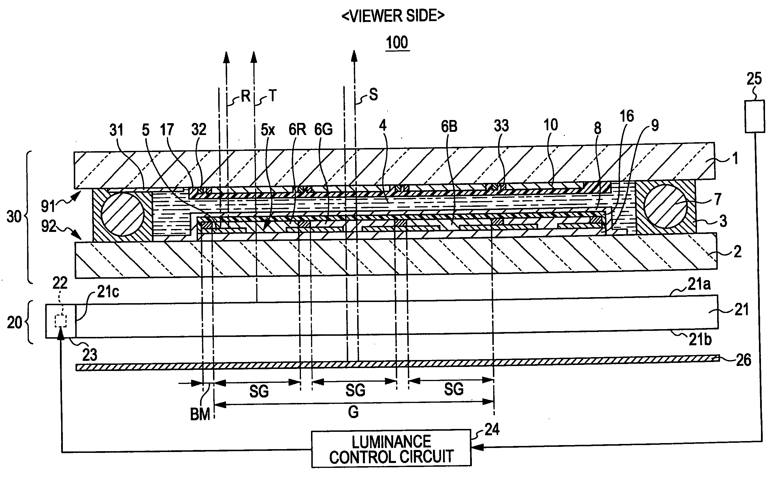
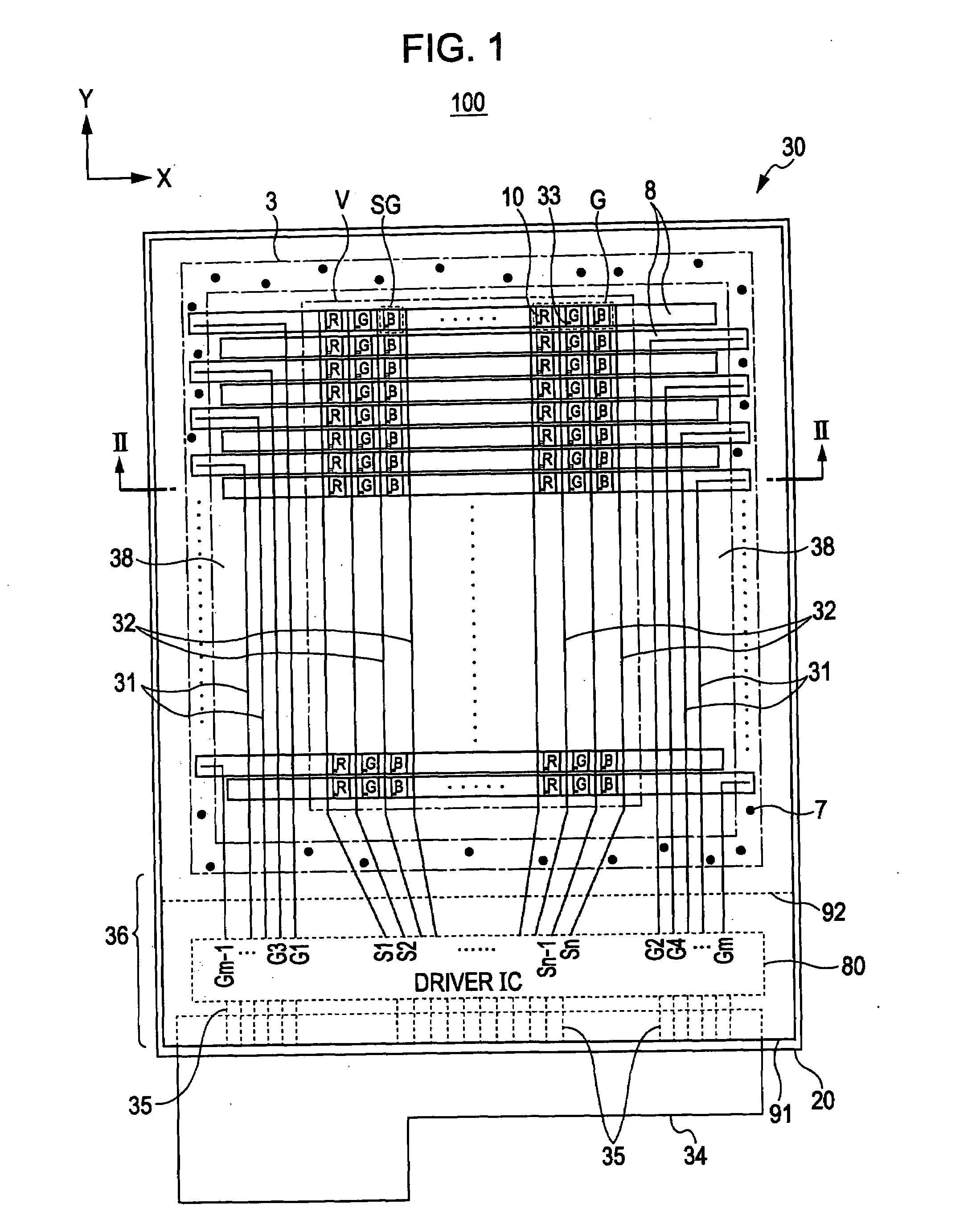
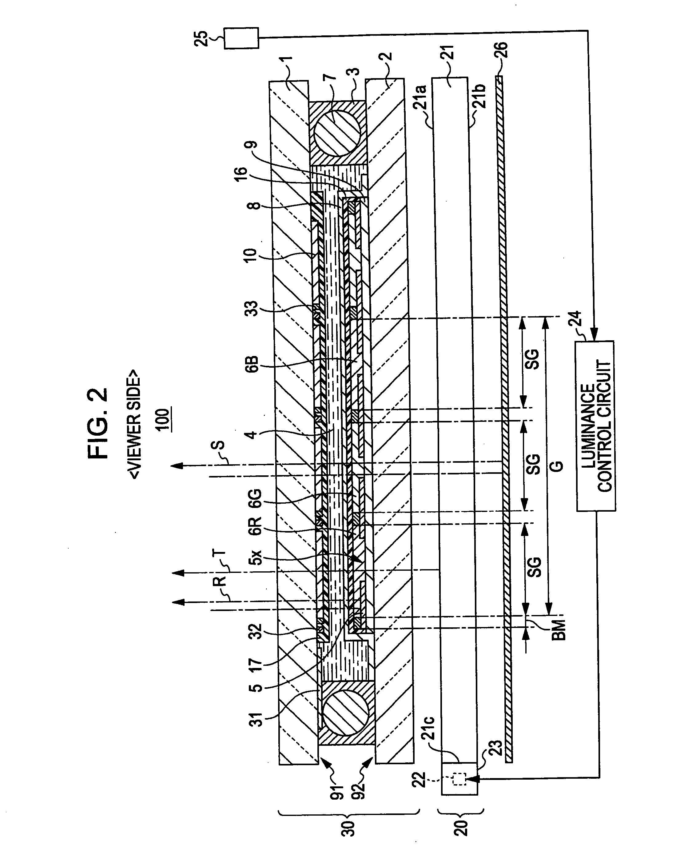
[0049]Referring to FIGS. 1 and 2, the structure of a liquid crystal device 100 according to an embodiment of the invention will be described. A display region in one subpixel region SG is herein referred to as “a subpixel” and a display region in a pixel region G is sometimes referred to as “a pixel”.

[0050]FIG. 1 is a schematic plan view of the liquid crystal device 100 according to the embodiment. The above in FIG. 1 is defined as Y-direction, and the right is defined as the X-direction for the convenience of description. The liquid crystal device 100 of this embodiment is a semitransmitting reflection liquid crystal device of an active matrix driving system using a thin-film diode (TFD) as an example of a two-terminal nonlinear element. FIG....


PUM


Abstract

An electrooptic device includes: a display panel; an illuminating unit that emits light onto the display panel; an ambient-light measuring unit that measures the illuminance of ambient light; a luminance control unit including a light control profile for obtaining the optimum surface luminance of the display panel, the luminance control unit obtaining the optimum surface luminance on the basis of the measured illuminance of the ambient light using the light control profile, and controlling the luminance of the light to be emitted from the illuminating unit to provide the display panel with the optimum surface luminance; a display-mode switching unit that switches the display panel to a transmission display mode when the illuminance of the ambient light measured by the ambient-light measuring unit is lower than a predetermined illuminance, and switches the display panel to a reflection display mode when the illuminance of the ambient light is higher than the predetermined illuminance; and a storage unit that stores a gamma value for the transmission display for the transmission display mode and a gamma value for the reflection display for the reflection display mode as a plurality of tables. When the display panel is switched to the transmission display mode by the display-mode switching unit, the gamma value for the transmission display is obtained from the plurality of tables stored in the storage unit, and the gamma value for the transmission display is applied. When the display panel is switched to the reflection display mode by the display-mode switching unit, the gamma value for the reflection display is obtained from the plurality of tables stored in the storage unit, and the gamma value for the reflection display is applied.

Description

[0001]The entire disclosure of Japanese Patent Application No. 2006-039203, filed Feb. 16, 2006 is expressly incorporated by reference herein.BACKGROUND[0002]1. Technical Field[0003]The present invention relates to electrooptic devices suitable for use in displaying various information.[0004]2. Related Art[0005]General liquid crystal devices have an illuminating unit on the back of a liquid-crystal display panel for transmission display. The general liquid crystal devices have used a constant-intensity light source both in light places and in dark places irrespective of extraneous light.[0006]However, humans feel even low-luminance light bright because the pupils of humans' visual sense dilate in dark places. Nevertheless, illuminating units illuminate the liquid-crystal display panel at constant luminance all the time. Accordingly, humans feel the illumination too bright in dark places to see the display screen. Moreover, illuminating units use the same constant-luminance light sou...

Claims


Application Information

Patent Timeline
IPC IPC(8): G09G3/36
CPCG09G3/3406G09G3/3413G09G3/3648G09G2300/0456G09G2360/144G09G2320/066G09G2320/0666G09G2320/0673G09G2320/043G02F1/133
Inventor KIMURA, FUSASHITAKAHASHI, MASAKITSUDA, ATSUNARI
Owner EPSON IMAGING DEVICES CORP
Why Eureka
Try Eureka