
Video signal conditioner of display device and video signal adjustment method thereof

a technology of video signal conditioner and display device, which is applied in the field ofsignal processing, can solve the problems of shortening the life of amoled display device, aging of tft and oled device, and higher power consumption, so as to control the luminance of display device, control the aging rate and cost of display device, and save storage space

Active Publication Date: 2019-07-23
SHENZHEN CHINA STAR OPTOELECTRONICS SEMICON DISPLAY TECH CO LTD
View PDF4 Cites 0 Cited by
  • Summary
  • Abstract
  • Description
  • Claims
  • Application Information

AI Technical Summary

Benefits of technology

[0023]Advantageous effects of the present disclosure: The present disclosure adjusts the video signal by controlling the luminance to be displayed by the pixels, thereby controls the luminance of the display device, and controls the aging rate and the costs of the display device. In addition, since the present disclosure controls the luminance to be displayed by the pixel in units of rows, in the adjustment process, only dynamically temporarily store data for each row of pixels, it can greatly save storage space.
of the present disclosure: The present disclosure adjusts the video signal by controlling the luminance to be displayed by the pixels, thereby controls the luminance of the display device, and controls the aging rate and the costs of the display device. In addition, since the present disclosure controls the luminance to be displayed by the pixel in units of rows, in the adjustment process, only dynamically temporarily store data for each row of pixels, it can greatly save storage space.

Problems solved by technology

Therefore, when the drive current is higher, the aging of TFT and OLED devices is faster, and the cost of power is higher.
Thus, it will shorten the life of AMOLED display device and increase the cost of the AMOLED display device.

Method used


Image

  • Video signal conditioner of display device and video signal adjustment method thereof
  • Video signal conditioner of display device and video signal adjustment method thereof

Examples


Embodiment Construction

[0028]Hereinafter, the embodiments of the present disclosure will be described in detail with reference to the accompanying diagrams. However, in many different forms and embodiments of the present disclosure, and the disclosure should not be construed as limited to the specific embodiments set forth herein. Rather, these embodiments are provided to explain the principles of the disclosure and its practical application so that others skilled in the art to understand the disclosure for various embodiments and various modifications suited to the particular intended application.

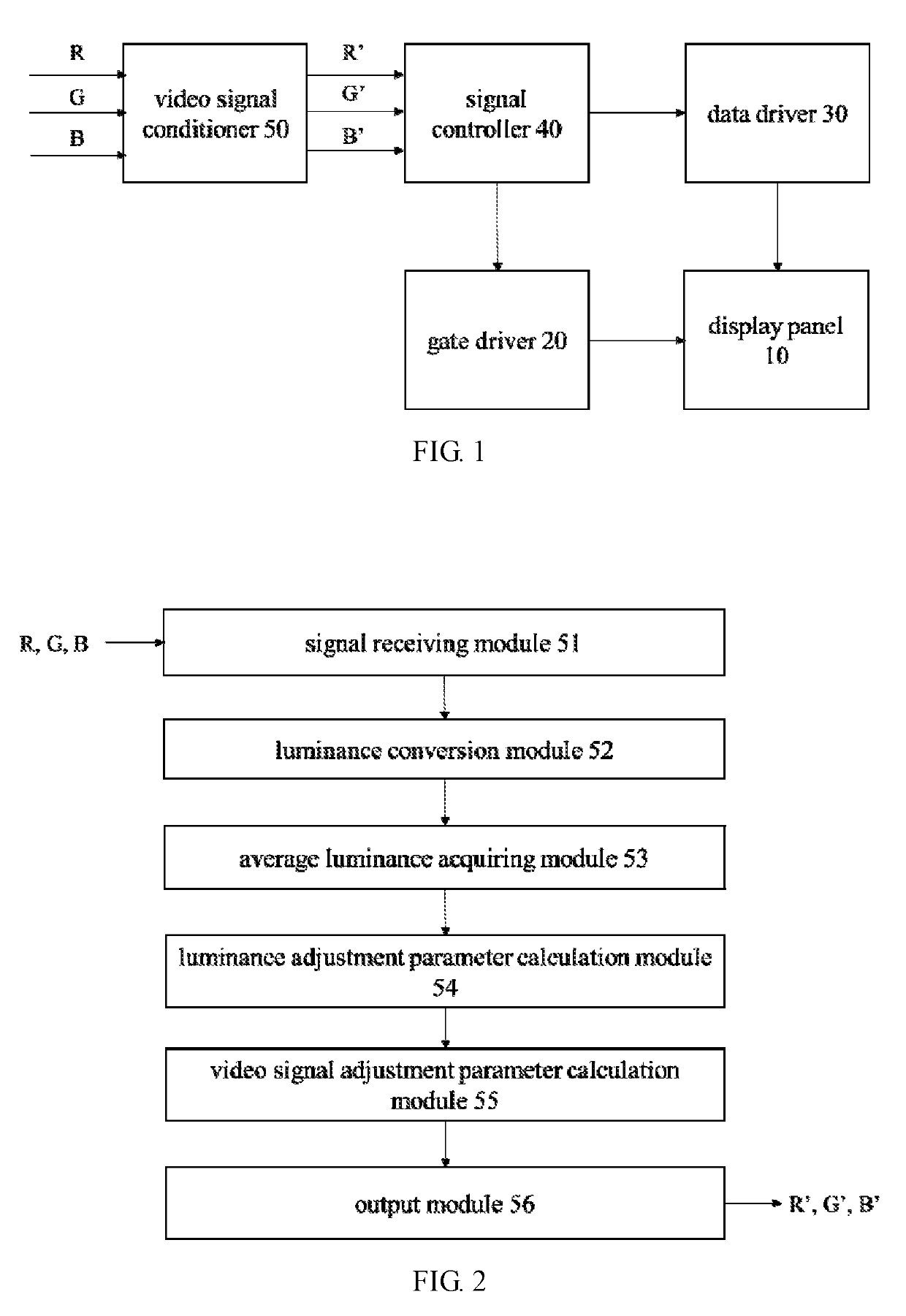
[0029]FIG. 1 is a block diagram showing an embodiment of a display device of the present disclosure.

[0030]Referring to FIG. 1, a display device according to an embodiment of the present disclosure comprises: a display panel 10, a gate driver 20, a data driver 30, a signal controller 40, and a video signal conditioner 50.

[0031]The display panel 10 comprises: a plurality of gate lines (not shown) extending in the ...


PUM


Abstract

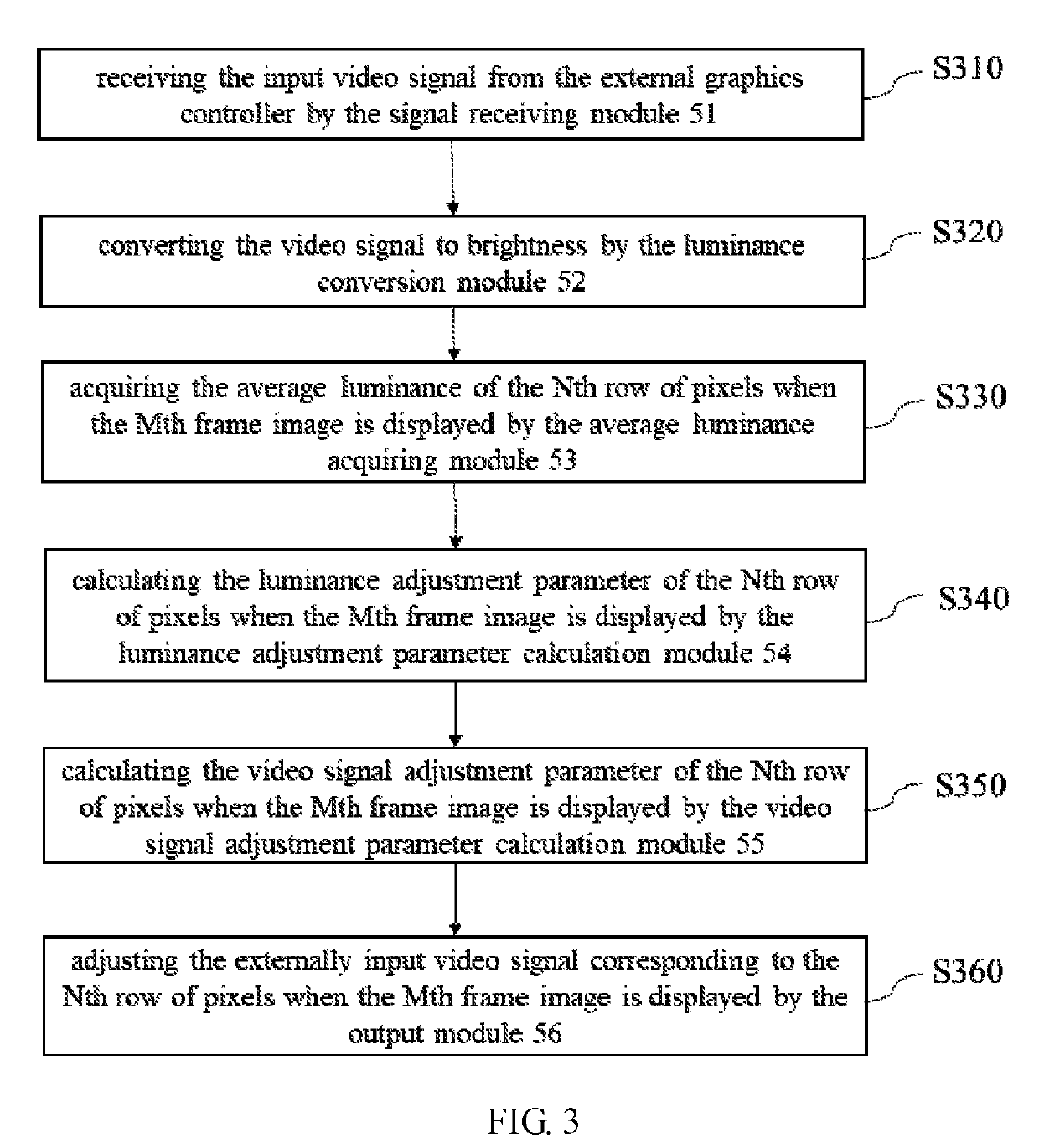
A video signal conditioner of a display device is provided. The video signal conditioner includes: a signal receiving module, for receiving an externally input video signal; a luminance conversion module, for converting the externally input video signal to brightness; an average luminance acquiring module, for acquiring an average luminance of a Nth row of pixels when a Mth frame image is displayed; a luminance adjustment parameter calculation module, for calculating a luminance adjustment parameter of the Nth row of pixels when the Mth frame image is displayed; a video signal adjustment parameter calculation module, for calculating a video signal adjustment parameter of the Nth row of pixels when the Mth frame image is displayed; an output module, for outputting the adjusted video signal corresponding to the Nth line of pixels when the Mth frame image is displayed.

Description

FIELD OF THE INVENTION[0001]The present disclosure belongs to a technical field of signal processing, and particularly relates to a video signal conditioner of display device and a video signal adjustment method thereof.BACKGROUND OF THE INVENTION[0002]An AMOLED (Active Matrix Organic Light Emitting Diode) display device is widely used because of its wider viewing angle, higher refresh rate and thinner thickness.[0003]In the AMOLED display device, the aging of TFT devices and OLED devices is positively correlated with the drive current, and the power drive capability is also positively correlated with the drive current. Therefore, when the drive current is higher, the aging of TFT and OLED devices is faster, and the cost of power is higher. Thus, it will shorten the life of AMOLED display device and increase the cost of the AMOLED display device.SUMMARY OF THE INVENTION[0004]In order to solve the above-mentioned problems of the current technology, the object of the present disclosur...

Claims


Application Information

Patent Timeline
Patent Type & Authority Patents(United States)
IPC IPC(8): G09G3/20G09G3/3225G09G3/3208
CPCG09G3/2096G09G3/3208G09G3/3225G09G2360/16G09G2320/043G09G2320/0626G09G2320/0646G09G2320/0295
Inventor HWANG, TAI-JIUNZENG, YUCHAO
Owner SHENZHEN CHINA STAR OPTOELECTRONICS SEMICON DISPLAY TECH CO LTD
Learn More