Display device and driving control method for the same

a technology of a display panel and a driving control method, which is applied in the direction of electric digital data processing, instruments, computing, etc., can solve the problems of complex control of the voltage or the like for each gray level of the display pixel, reducing the number of gray levels available for expression, and reducing the display. the effect of luminance control

Inactive Publication Date: 2010-03-18
SOLAS OLED LTD
View PDF9 Cites 14 Cited by
  • Summary
  • Abstract
  • Description
  • Claims
  • Application Information

AI Technical Summary

Benefits of technology

[0012]The present invention provides a display device enabling the luminance of a display panel to be controlled without the need to vary the gray level of image information displayed on the display panel, depending on the brightness of a surrounding environment or the like, as well as a driving control method for the display device.

Problems solved by technology

However, simply providing display using only low gray levels reduces the number of gray levels available for expression, thus degrading the display.
However, since the voltage range is varied with gray level, the control of the voltage or the like for each gray level for each display pixel is complicated.

Method used


Image

  • Display device and driving control method for the same
  • Display device and driving control method for the same
  • Display device and driving control method for the same

Examples


first embodiment

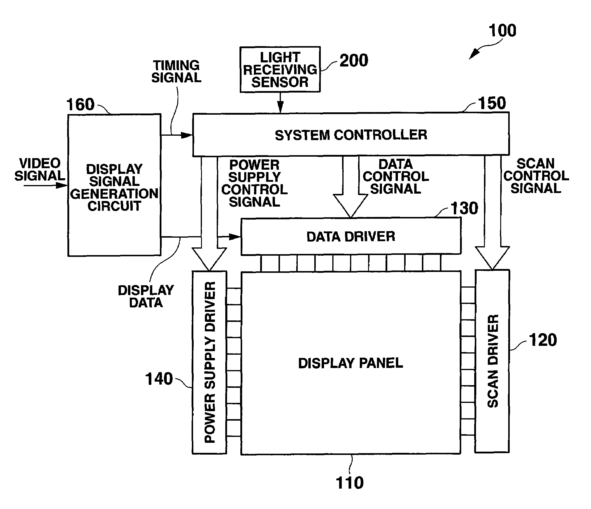
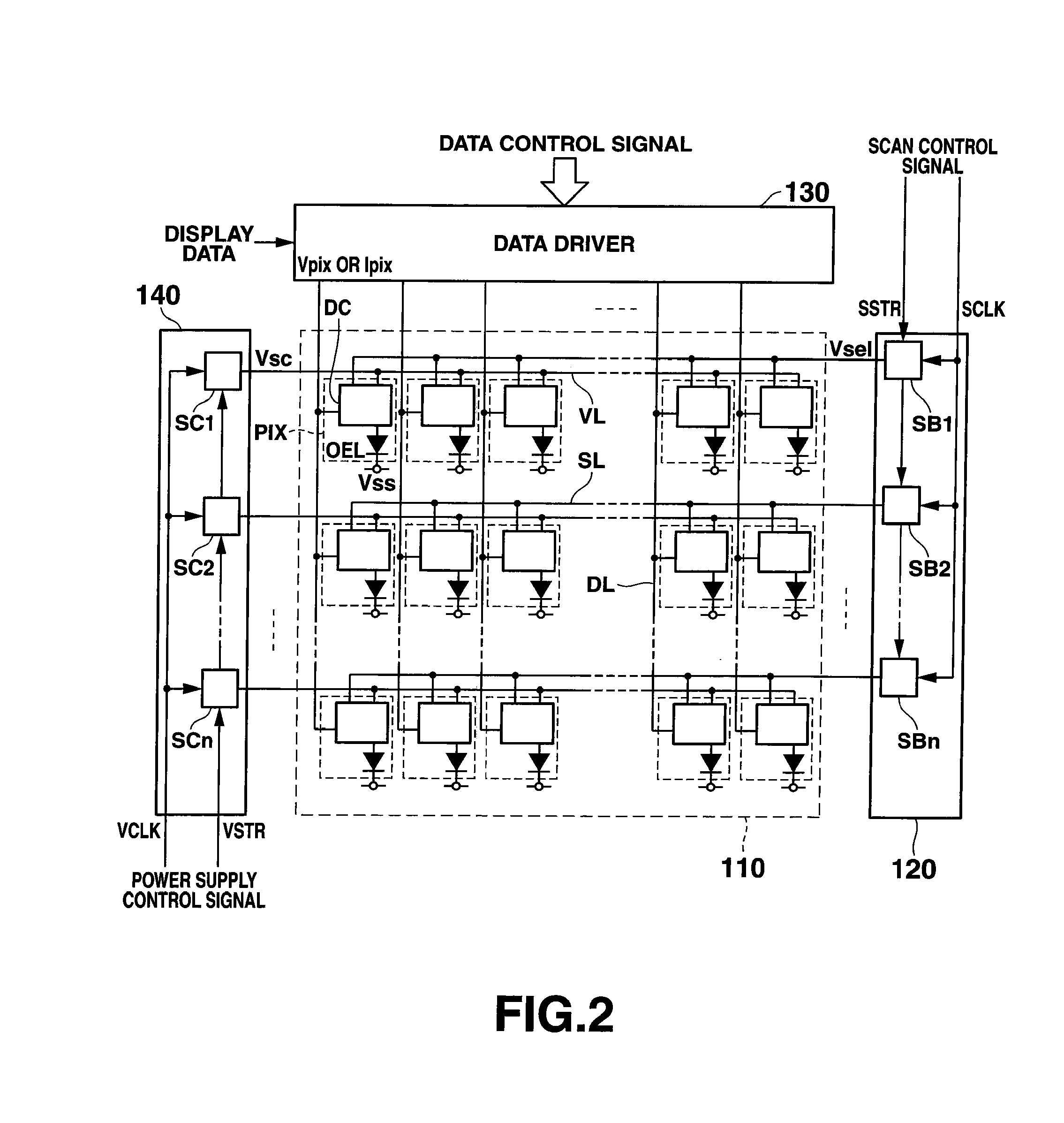
[0036]First, a first embodiment of the present invention will be described. FIG. 1 is a diagram showing the general configuration of a display panel driving device. FIG. 2 is a diagram showing the configuration of a display panel and drivers in the display panel driving device.

[0037]A display panel driving device (display device) 100 includes a display panel (pixel array) 110. A plurality of scan lines SL, a plurality of power supply lines VL, and a plurality of data lines (signal lines) DL are arranged in the display panel 110. The plurality of scan lines SL are disposed parallel to one another. The plurality of power supply lines VL are disposed along the scan lines. The plurality of data lines DL cross the scan lines SL and the power supply lines VL at right angles.

[0038]A plurality of display pixels PIX are arranged near the respective intersecting points between the scan line L and the power supply line VL and the plurality of data lines DL. Each of the plurality of display pix...

second embodiment

[0147]Now, a second embodiment of the present invention will be described. The configuration of the display panel driving device is the same as that shown in FIGS. 1 to 4 and will thus not be described below.

[0148]In the first embodiment, while a write operation is being performed on the organic electroluminescent elements GEL in each of the rows in one partitioned display area set to the non-light-emission operation state, the light emission operation state is set for the partitioned display areas set to the light emission operation state throughout the period in which the write operation is performed on the organic electroluminescent elements GEL in all the rows in the one partitioned display area set to the non-light-emission operation state.

[0149]In contrast, the second embodiment offers, in addition to the characteristics of the first embodiment, the following characteristic. The period during which a write operation is performed on the organic electroluminescent elements OEL i...

third embodiment

[0165]Now, a third embodiment of the present invention will be described. The configuration of the display panel driving device is the same as that in FIGS. 1 to 4 described above and will thus not be described in detail.

[0166]FIGS. 13A and 13B are diagrams showing the connection configuration of a plurality of power supply lines VL in a display panel 110 and a power supply driver 140. FIG. 13A shows the entire connection configuration of the display panel 110 and the power supply driver 140. FIG. 13B is an enlarged view of a part of the connection configuration of the display panel 110 and the power supply driver 140 illustrating the configuration of partitioned display areas H1 to H8.

[0167]The display area of the display panel 110 is partitioned into the eight partitioned display areas H1 to H8 as is the case with the first and second embodiments. The same number of a plurality of power supply lines VL, for example, eight power supply lines VL, are arranged in each of the partitio...


PUM


Abstract

A display device includes a display panel having a display area in which a plurality of display pixels are two-dimensionally arranged, to display image information, a power supply driving section applying, to each of the display pixels in the display area, one of a first power supply voltage having a voltage value at which the display pixel is set to a non-display-operation state and a second power supply voltage having a voltage value at which the display pixel is set to a display operation state, and a control section controlling the power supply driving section to set a area-ratio of an first area in the display area in which the display pixels to which the first power supply voltage is applied are arranged to an second area in which the display pixels to which the second power supply voltage is applied are arranged.

Description

CROSS-REFERENCE TO RELATED APPLICATIONS[0001]This application is based upon and claims the benefit of priority from prior Japanese Patent Application No. 2008-237110, filed Sep. 16, 2008, the entire contents of which are incorporated herein by reference.BACKGROUND OF THE INVENTION[0002]1. Field of the Invention[0003]The present invention relates to a display device including, for example, a plurality of organic electroluminescent elements arranged in a matrix, and a driving control method for the display device.[0004]2. Description of the Related Art[0005]Conventional self-luminous light emitting elements include, for example, organic electroluminescent elements, inorganic electroluminescent elements, and light emitting diodes (LEDs). Light-emitting element displays (display devices) are known which include a display panel in which such self-luminous light emitting elements are arranged in a matrix.[0006]In particular, light-emitting element displays to which an active matrix drivin...

Claims


Application Information

Patent Timeline
Patent Type & Authority Applications(United States)
IPC IPC(8): G09G5/00
CPCG09G3/2081G09G3/3225G09G3/3258G09G3/3266G09G2300/0866G09G2360/144G09G2310/0218G09G2320/0247G09G2320/0606G09G2320/064G09G2310/0216
Inventor OZAKI, TSUYOSHI
Owner SOLAS OLED LTD
Why Eureka
Try Eureka