

Liquid crystal display
- Summary
- Abstract
- Description
- Claims
- Application Information
AI Technical Summary
Benefits of technology
Problems solved by technology
Method used
Image

Examples
embodiment
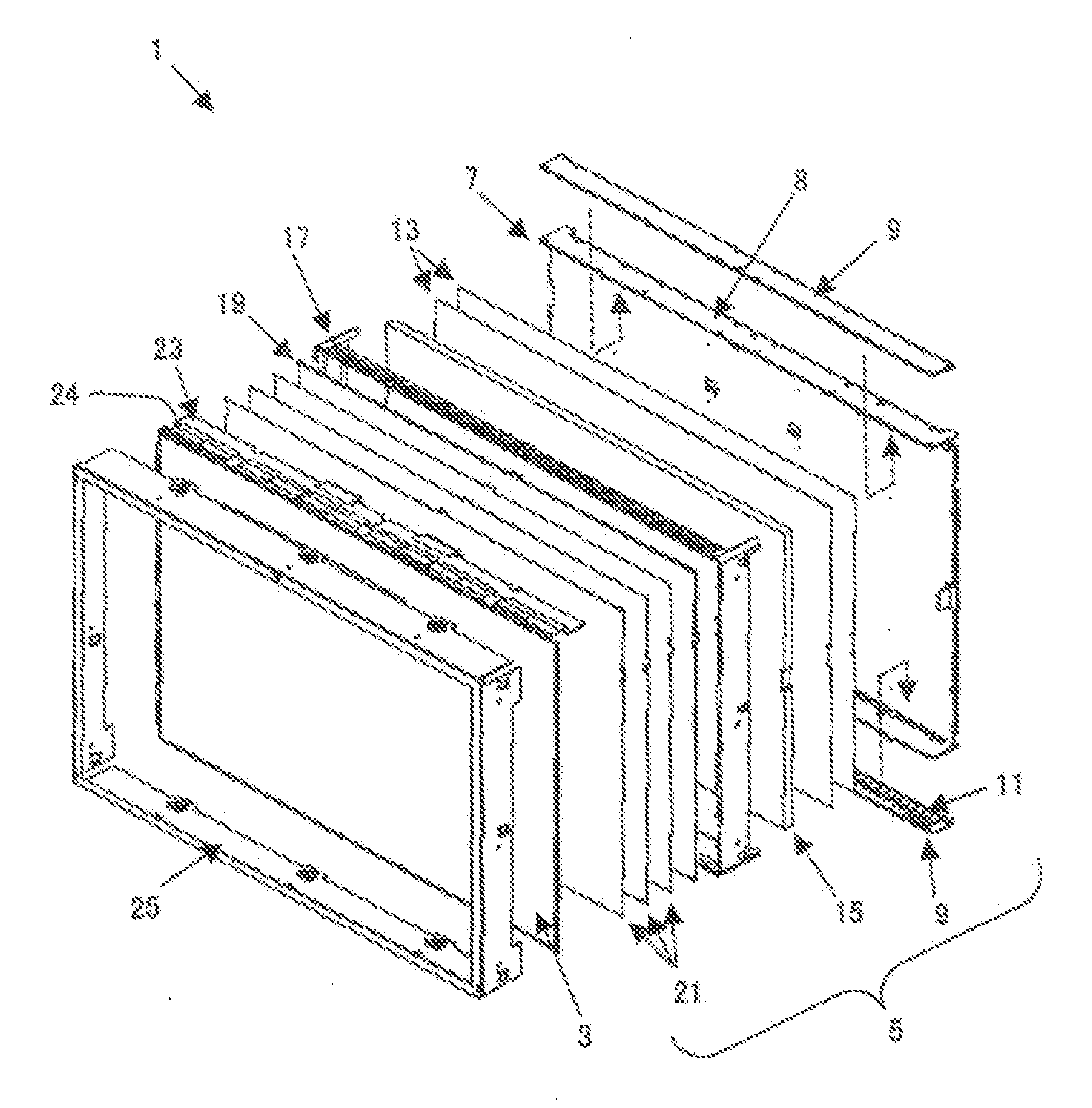
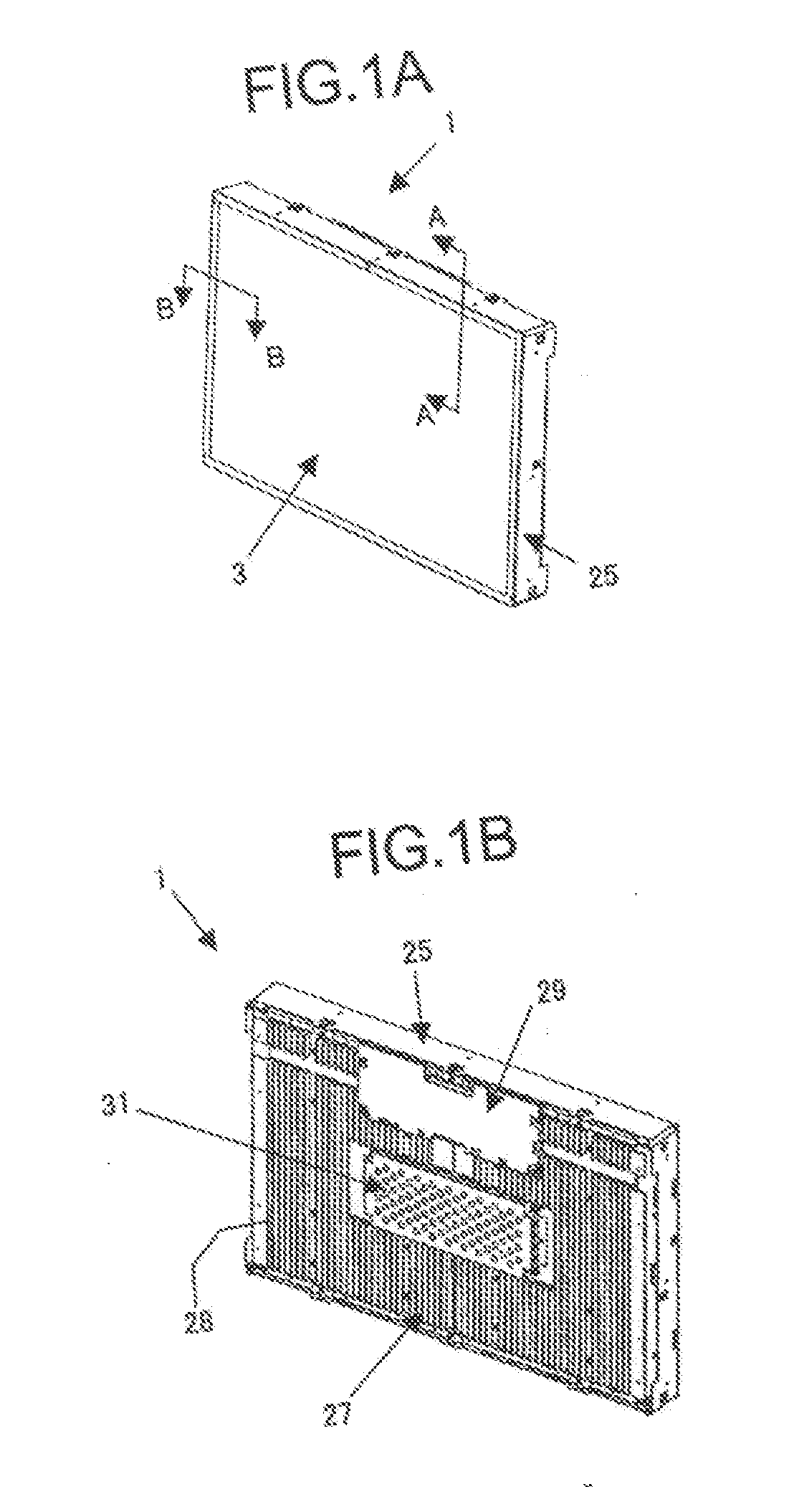
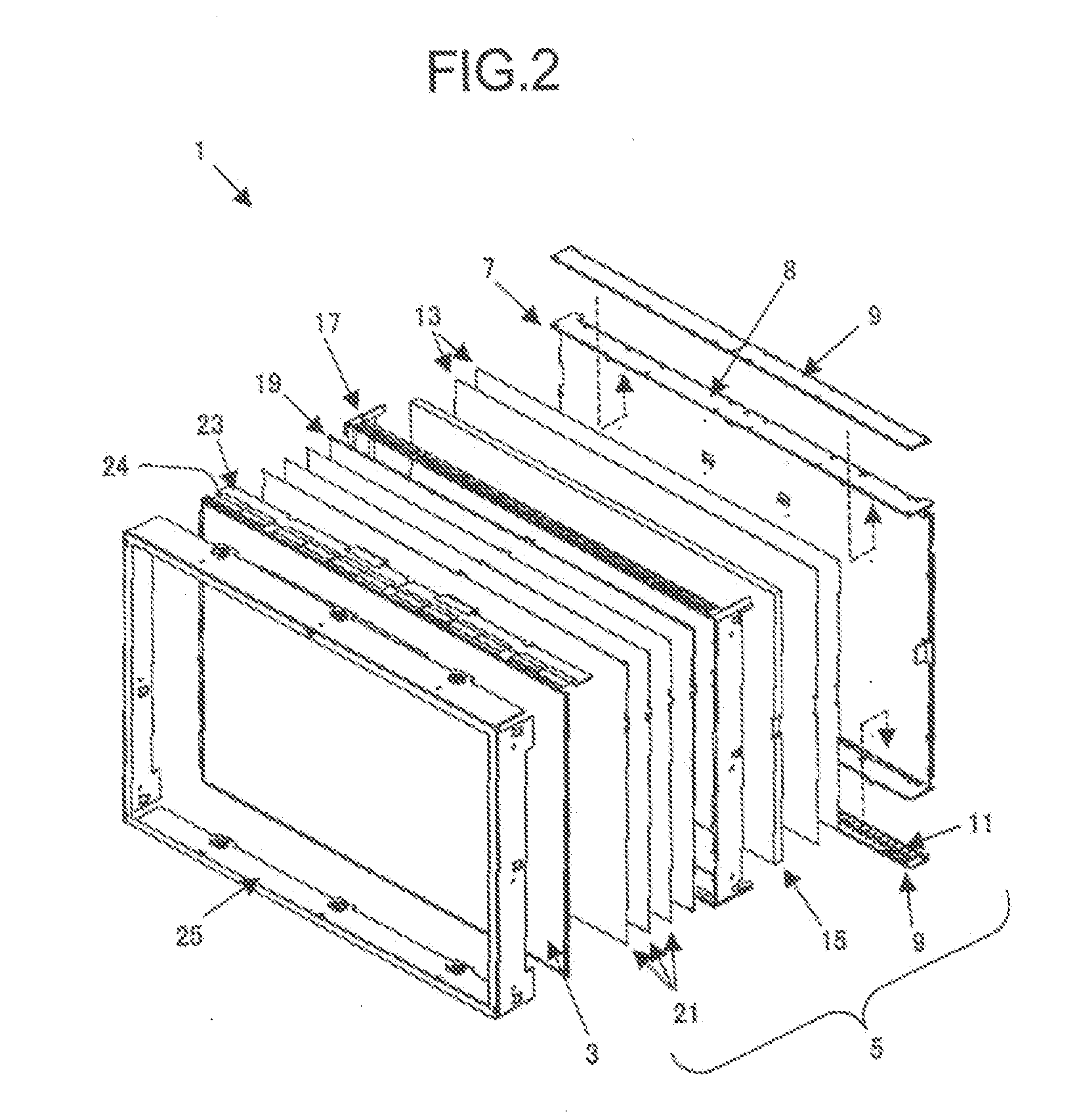
[0035] A liquid crystal display according to the present embodiment will now be described with reference to FIGS. 3 to 14. FIG. 3 is a sectional view of a liquid crystal display 1 taken along an imaginary line A-A in FIG. 1A. As shown in FIG. 3, a recess 37 is formed at an upstanding portion 8 of a rear frame 7. An LED module 9 is provided on a side of the upstanding portion 8 facing a light guide body 15. The LED module 9 includes a plurality of LEDs 11 and a circuit substrate 51 on which the plurality of LEDs 11 are mounted. The LEDs 11 and the light guide body 15 can be easily located by disposing the LED module 9 in a part of the recess 37. A data substrate 23 is provided between the upstanding portion 8 and a cosmetic cover 25. The data substrate 23 is electrically connected to a control substrate 29 through an FPC 33.
[0036] A diffusing member 19 is formed from a material having a high Young's modulus. A space 35 equivalent to the thickness of a front frame 17 is defined betwe...
PUM
 Abstract
Description
Claims
Application Information