Combined-type steel bridge deck laying method

A combined, steel deck technology, applied in bridges, bridge parts, bridge construction, etc., can solve the problems of large deformation of the steel deck system, hidden dangers, low adhesion of bridge deck steel plates, etc., to achieve strong deformation resistance, The effect of strong shear resistance and good followability

Active Publication Date: 2018-11-13
广州珠江黄埔大桥建设有限公司 +2
View PDF5 Cites 0 Cited by
  • Summary
  • Abstract
  • Description
  • Claims
  • Application Information

AI Technical Summary

Problems solved by technology

For the technical indicators of the aggregate, the construction site usually checks the physical indicators according to the relevant technical indicators of the "Highway Engineering Aggregate Test Regulations", and the adhesion to the epoxy asphalt binder can also be controlled according to the ordinary asphalt index (≥4). It is difficult for epoxy asphalt mixture to really meet the requirements; at the same time, there will be insufficient or unstable supply of material sources on site, resulting in large changes in the field use and testing of aggregates. Carry out system testing and rush construction
For the selection of slag powder, the physical indicators such as its fineness and hydrophobicity are mainly considered, and it is sufficient not to contain active lime, but there is no additional requirement for harmful impurities in it. If the slag powder is doped with metal minerals, it may be dama

Method used


Image

  • Combined-type steel bridge deck laying method
  • Combined-type steel bridge deck laying method
  • Combined-type steel bridge deck laying method

Examples


Example Embodiment

[0025] In order to make those skilled in the art better understand the technical solutions of the present invention, the present invention will be described in further detail below with reference to the accompanying drawings and specific embodiments. and features of the embodiments may be combined with each other.

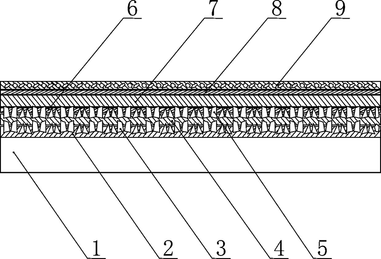
[0026] like figure 1 As shown, a composite steel bridge deck paving method includes the following steps:

[0027] A. Laying modified epoxy resin crushed stone combined connection layer:

[0028] ①Sand blasting to Sa2.5 on the surface of steel plate 1 of the steel bridge deck to remove dust, dry and pollution-free;

[0029] ② Measure the A and B components of the modified epoxy resin in a ratio of 1:1 and pour them into a clean container, stir until the liquid is mixed to a uniform state, and the stirring time should not be less than 3min. Oxygen resin according to the set dosage 1.0 ~ 1.5kg / m 2 Evenly spread on the surface of the steel plate to form the first m...


PUM

PropertyMeasurementUnit
Thicknessaaaaaaaaaa
Thicknessaaaaaaaaaa
Thicknessaaaaaaaaaa

Abstract

The invention discloses a combined-type steel bridge deck laying method. The combined-type steel bridge deck laying method comprises the following steps that A, a modified epoxy resin and gravel combined-type connection layer is laid, specifically, the surface of a steel plate of a steel bridge deck is subjected to sandblasting shot blasting, modified epoxy resin is laid and smeared on the surfaceof the steel plate to form a first modified epoxy resin layer, gravel is scattered on the surface of the first modified epoxy resin layer to form a first gravel layer, modified epoxy resin is evenlylaid and smeared on the surface of the first gravel layer according to the set dosage to form a second modified epoxy resin layer, and then gravel is scattered to form a second gravel layer; and B, ultra-high performance pavement is laid, specifically, active epoxy asphalt or high-viscosity modified emulsified asphalt is smeared on the surface of the connection layer to form a first waterproof bonding layer, then a stone mixture is laid and smeared to form a waterproof-type structure layer, and finally integrated spreading of a second waterproof bonding layer and a drainage-type abrasion layeris conducted through special equipment. According to the combined-type steel bridge deck laying method, sliding and delaminating between the structural layers are prevented, and the stability and durability of the structure are guaranteed.

Description

technical field [0001] The invention relates to a cable load-bearing structure bridge construction method, in particular to a combined steel bridge deck paving method for a large-span cable load-bearing structure bridge. Background technique [0002] In the past two decades, many long-span cable-bearing structure bridges have been built in my country, and the main girder structure is basically made of orthotropic steel panels and thin-layer pavement to form the bridge traffic system structure. The orthotropic steel bridge deck structure is composed of transverse diaphragm beams, longitudinal stiffeners and the bridge deck supported together. The elastic properties of the bridge deck structure in the transverse and longitudinal directions are different, and the stiffness of the bridge deck in different positions in the same direction is also different. These factors The inhomogeneity of stiffness and deformation of the orthotropic steel bridge deck is formed. In addition, the...

Claims


Application Information

Patent Timeline
IPC IPC(8): E01D19/00
CPCE01D19/00
Inventor 张少锦刘先淼邓志华王勇
Owner 广州珠江黄埔大桥建设有限公司
Why Eureka
Try Eureka