Luminance-enhancing film, optical sheet member, and liquid crystal display device

Active Publication Date: 2016-06-16
FUJIFILM CORP
View PDF11 Cites 23 Cited by
  • Summary
  • Abstract
  • Description
  • Claims
  • Application Information

AI Technical Summary

Benefits of technology

[0035]According to the present invention, it is possible to provide a luminance-enhancing film which has high luminanc

Problems solved by technology

In the technology disclosed in JP3448626B and JP1989-133003A (JP-H01-133003A), a light utilization rate is enhanced in broadband with respect to the white light, and thus a problem occurs in which manufacturing costs increase on complicated design in consideration of a multilayer configuration and wavelength dispersion properties of the member.
On the other hand, the liqu

Method used


Image

  • Luminance-enhancing film, optical sheet member, and liquid crystal display device
  • Luminance-enhancing film, optical sheet member, and liquid crystal display device
  • Luminance-enhancing film, optical sheet member, and liquid crystal display device

Examples


Example

[0081]FIG. 7 is the configuration of the optical sheet member of Comparative Example 5, and FIG. 8 is the configuration of the optical sheet member of Example 12 which is an optical sheet member of the present invention.

[0082]In FIG. 7 relevant to the optical sheet member of Comparative Example 5, a blue light (B) reflection layer of which the cholesteric liquid crystal material is a rod-like liquid crystal compound, a red light (R) reflection layer of which the cholesteric liquid crystal material is a rod-like liquid crystal compound, a green light (G) reflection layer of which the cholesteric liquid crystal material is a rod-like liquid crystal compound, a λ / 4 plate (a vertical alignment layer of a disk-like liquid crystal compound), a support, and a polarizer are laminated in this order from the light source side. A transmission axis of the polarizer is in a 0° direction, and a slow axis of the λ / 4 plate is in a 45° direction.

Example

[0083]In contrast, in FIG. 8 relevant to the optical sheet member of Example 12 which is the optical sheet member of the present invention, the red light (R) reflection layer of which the cholesteric liquid crystal material is the rod-like liquid crystal compound in FIG. 7 is replaced by a red light reflection layer of which the cholesteric liquid crystal material is a disk-like liquid crystal compound.

[0084]First, in the optical sheet member of Comparative Example 5 illustrated in FIG. 7, the occurrence of oblique shade will be described by using a Poincare sphere illustrated in FIGS. 10A and 10B. FIGS. 10A and 10B are diagrams when the Poincare sphere is seen from an S3 axis direction.

[0085]First, in FIG. 10A, transition of a polarization state of blue light (wavelength=465 nm) which is incident at a polar angle of 60° in a slow axis direction of the polarizer will be described. Hereinafter, the light incident on each of the members at a polar angle of 60° in the slow axis directi...

Example

[0117]In an optical sheet member having the same configuration as that in Example 11 which is shown in the second column from the left side of Table 1, each transition of the polarization state of the blue light and the green light incident at a polar angle of 60° in the slow axis direction of the polarizer is illustrated in FIG. 12A and FIG. 12B. FIGS. 12A and 12B are diagrams when the Poincare sphere is seen from the S3 axis direction.

[0118]Furthermore, the transmittance balance between the blue light, the green light, and the red light is able to be changed not only by properties of the liquid crystal material of the first light reflection layer and the second light reflection layer but also by changing Re and Rth of the λ / 4 plate and the support.

[0119]

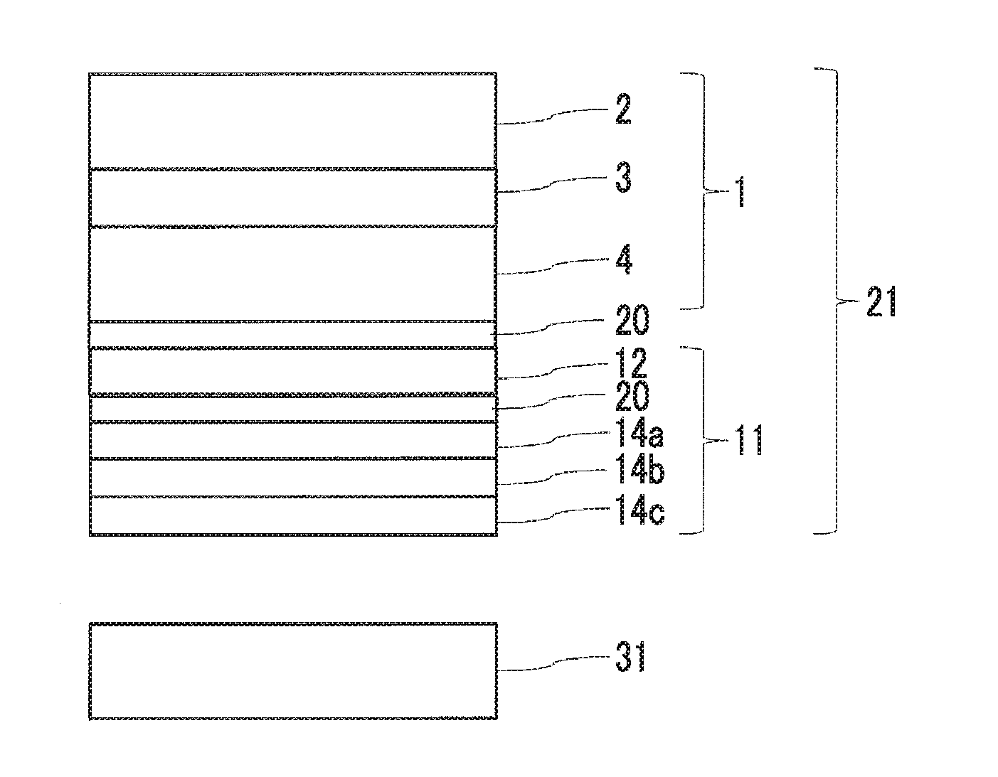
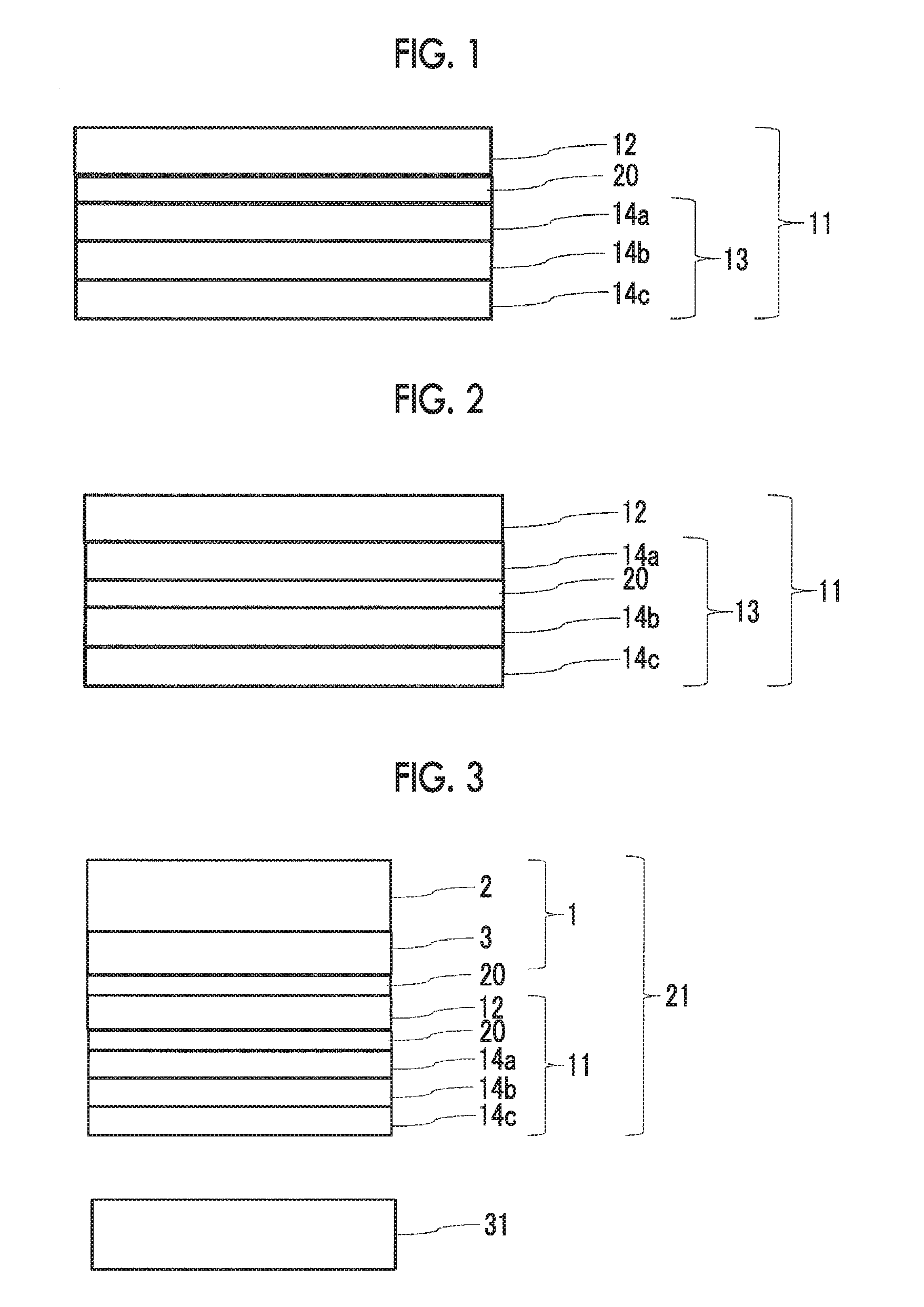
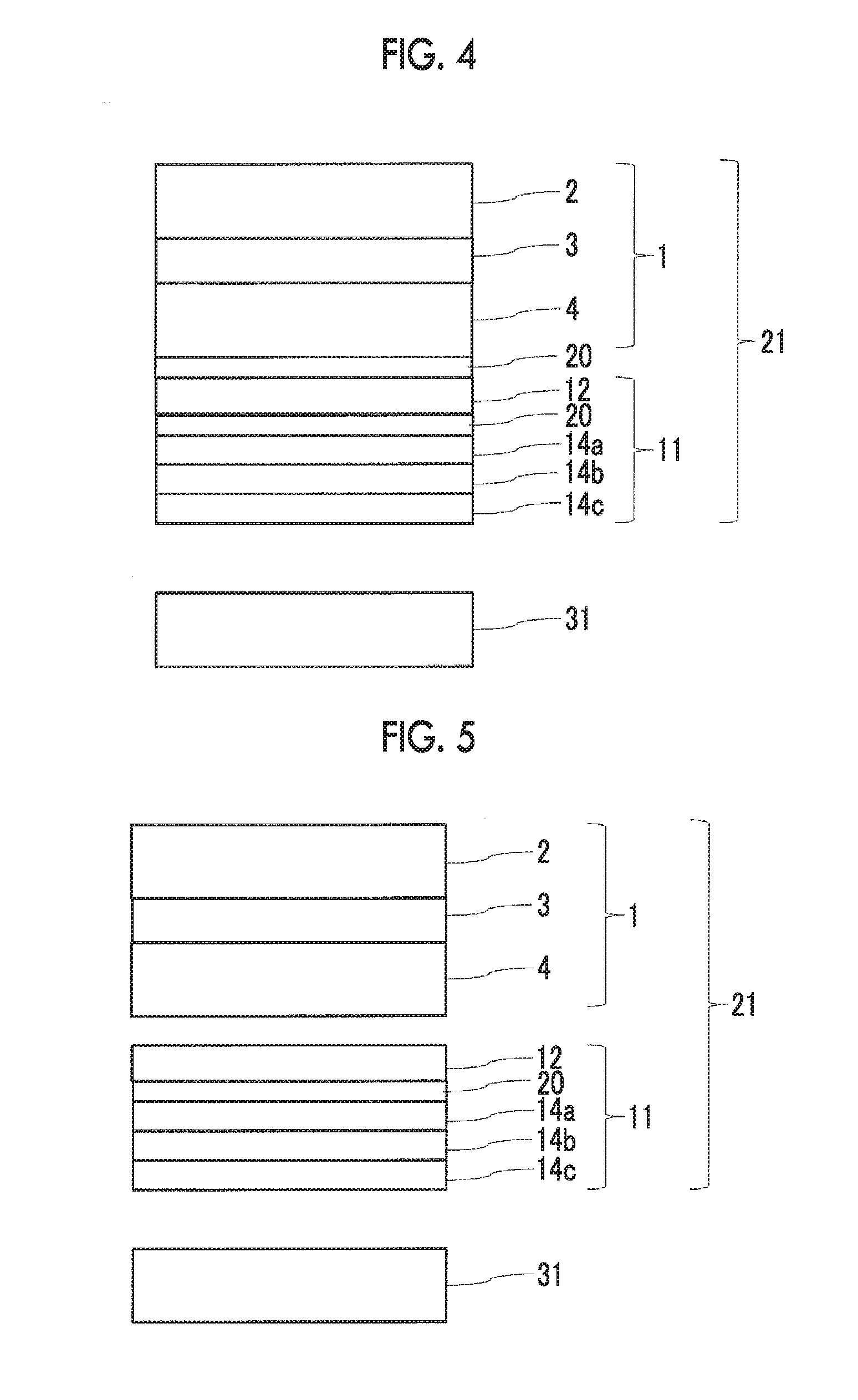
[0120]The configuration of the luminance-enhancing film of the present invention will be described with reference to the drawings.

[0121]In FIG. 1, an aspect is illustrated in which a reflection polarizer 13 formed of three layers o...


PUM


Abstract

The present invention provides a luminance-enhancing film including a λ/4 plate, and a reflection polarizer, including a first light reflection layer, a second light reflection layer, and a third light reflection layer from the λ/4 plate side sequentially, the light reflection layers being light reflection layers formed by fixing a cholesteric liquid crystalline phase, and including blue, green and red light reflection layers, and Rth(550) of the first light reflection layer and Rth(550) of the second light reflection layer having inverse signs; and a luminance-enhancing film including a λ/4 plate and a reflection polarizer including at least a light reflection layer formed of a rod-like cholesteric liquid crystal material and a light reflection layer formed of a disk-like cholesteric liquid crystal material. The luminance-enhancing film has high luminance and is able to suppress an oblique change in the color.

Description

CROSS-REFERENCE TO RELATED APPLICATIONS[0001]This application is a continuation of PCT International Application No. PCT / JP2014 / 072209 filed on Aug. 26, 2014, which claims priorities under 35 U.S.C §119 (a) to Japanese Patent Applications Nos. 2013-174971, 2014-026581 and 2014-057848 filed on Aug. 26, 2013, Feb. 14, 2014, and Mar. 20, 2014, respectively, the entire contents of which are incorporated herein by reference.BACKGROUND OF THE INVENTION[0002]1. Field of the Invention[0003]The present invention relates to a luminance-enhancing film, an optical sheet member, and a liquid crystal display device. More specifically, the present invention relates to a luminance-enhancing film which has high luminance and is able to suppress an oblique color change at the time of being incorporated in a liquid crystal display device, an optical sheet member using the luminance-enhancing film, and a liquid crystal display device using the luminance-enhancing film.[0004]2. Description of the Relate...

Claims


Application Information

Patent Timeline
IPC IPC(8): G02B5/30G02F1/13363G02F1/1335
CPCG02B5/3041G02F1/133603G02F1/133621G02F1/13363G02F2001/133543G02B5/3016G02F2001/133614G02F2001/133638G02F1/133536G02B5/26G02F1/133634G02F1/133543G02F1/133638G02F1/133614
Inventor WATANO, AKIKOSAITOH, YUKITOOHMURO, KATSUFUMIICHIHASHI, MITSUYOSHIISHIKAWA, HIROYUKIYASUDA, KOTARONISHIKAWA, HIDEYUKIMATSUDA, YUKIHOSHINO, WATARU
Owner FUJIFILM CORP
Why Eureka
Try Eureka