Image display apparatus

Inactive Publication Date: 2012-06-21
CANON KK
View PDF1 Cites 21 Cited by
  • Summary
  • Abstract
  • Description
  • Claims
  • Application Information

AI Technical Summary

Benefits of technology

[0012]The image display apparatus of the present invention performs a conversion processing such that, the nearer a changing quantity of the common logarithm of the luminance to be assigned to the increment of the gradation approaches the maximum value of the gradation, the larger the changing quantity becomes. Accordingly, reduction in human ability of discriminating the variation quantity of the common logarithm of the luminance in the high luminance and gradation range can be compensated. Therefore, the gradation-display luminance converting chara

Problems solved by technology

However, the nearer the luminance approaches the lowest limit discriminable to humans, the more diffi

Method used


Image

  • Image display apparatus
  • Image display apparatus
  • Image display apparatus

Examples


Example

Example 1

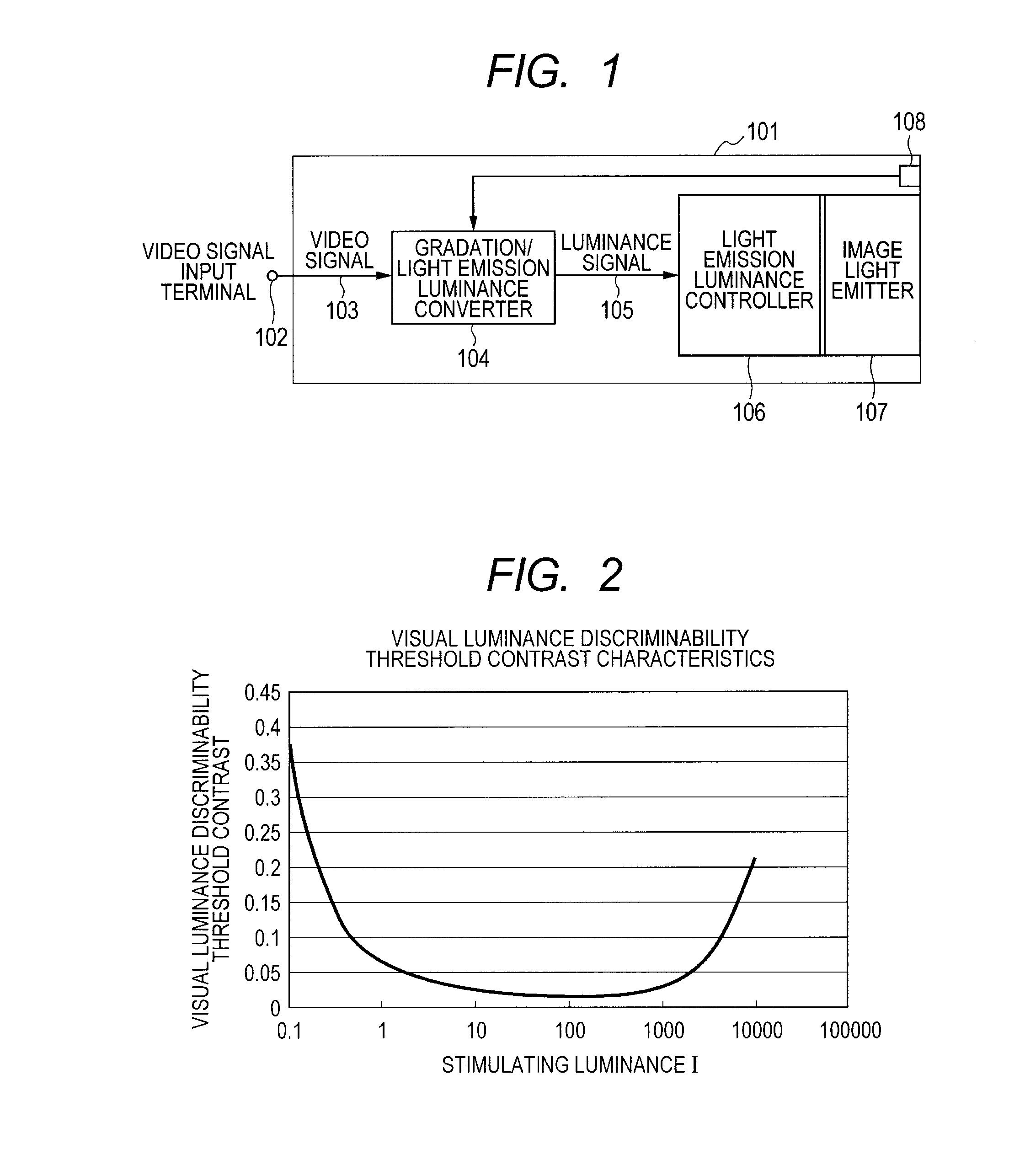
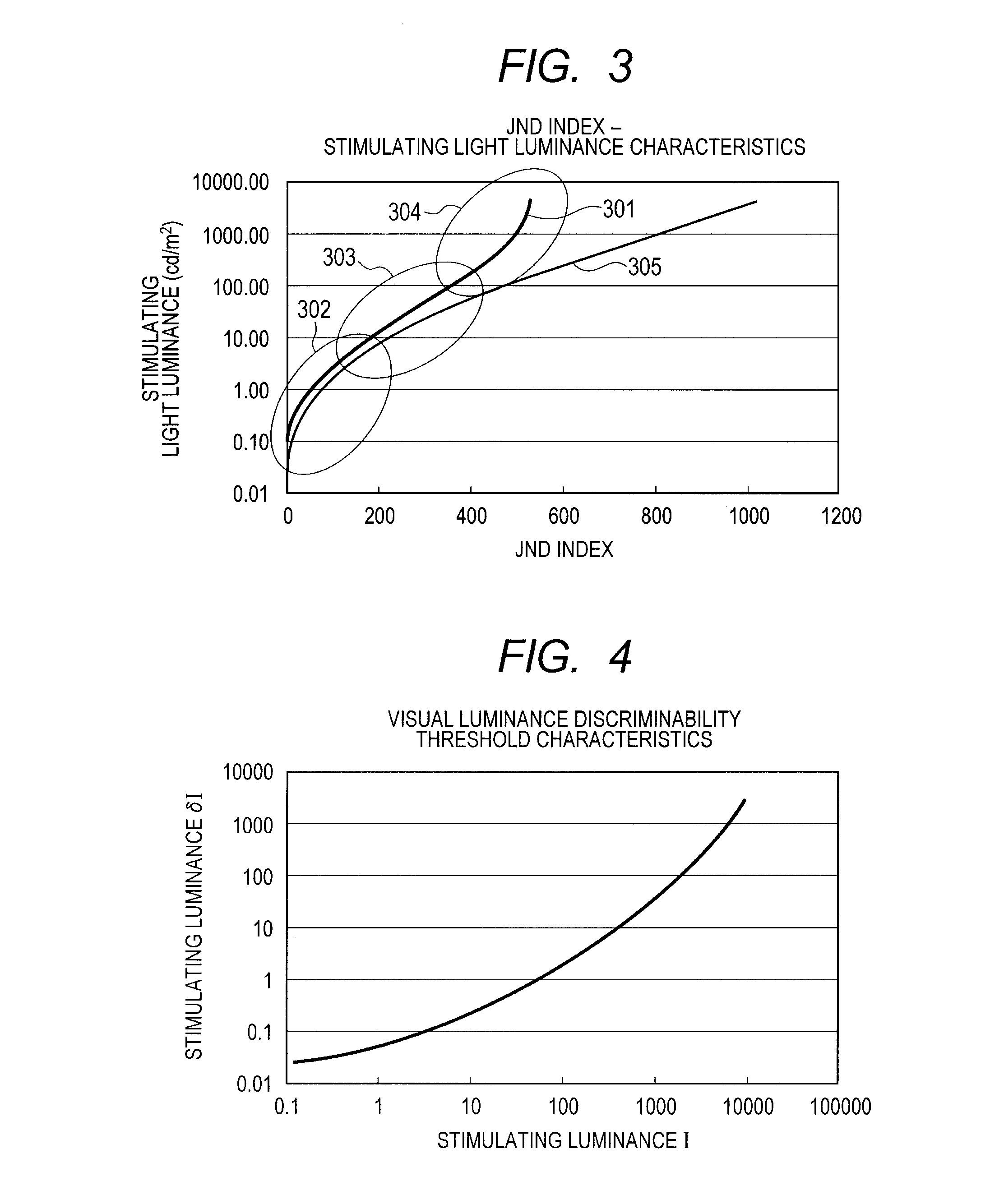
[0061]FIG. 1 is a diagram of a configuration of a video display apparatus of an example. FIG. 2 is a diagram of luminance discriminability threshold contrast characteristics with respect to incident light luminances. FIG. 3 is a diagram of visual stimulating light luminance characteristics with respect to JND index. FIG. 4 is a diagram of luminance discriminability threshold characteristics with respect to stimulating light luminances. FIG. 5 is a diagram of light emitting luminance characteristics with respect to input signal levels. FIG. 6 is a signal conversion quadrant diagram from input of a video signal to light emitting.

[0062]As illustrated in FIG. 1, in a video display apparatus 101, a video signal transmitted from a video source, which is not illustrated, is captured as a video signal 103 in the video display apparatus 101 via a video signal input terminal 102. The signal format of the video signal 103 may be various depending on types of video sources. In this exa...

Example

Example 2

[0111]FIG. 7 is a diagram of luminance discriminability threshold contrast characteristics with respect to incident light luminances in Example 2. FIG. 8 is a diagram of visual stimulating light luminance characteristics with respect to JND index in Example 2. FIG. 9 is a diagram of light emitting luminance characteristics with respect to input signal levels in Example 2.

[0112]Example 2 is configured and controlled in the same manner as Example 1 except for that characteristics of the gradation-display luminance converting LUT implemented in the gradation / light emission luminance converter 104 of the video display apparatus 101 are different from those of Example 1. Accordingly, a difference with Example 1 in the characteristics of the gradation-display luminance converting LUT will hereinafter be described, and the other redundant description will be omitted.

[0113]FIG. 7 is a diagram representing luminance discriminability threshold contrast characteristics with respect to...

Example

Example 3

[0143]FIG. 15 is a block diagram illustrating a configuration of a video display apparatus according to Example 3. FIGS. 16A to 16C is a schematic diagram illustrating a relation between luminances of light incident in the eyes and luminance difference discriminability threshold contrast. FIG. 17 is a flowchart illustrating of an operation of a unit setting light emitting luminance characteristics according to Example 3. FIG. 18 is a schematic diagram illustrating light emitting luminance characteristics. FIGS. 4 to 6 are diagrams illustrating light emitting luminance characteristics that convert gradations of an image into luminances of the displaying. FIG. 9 is a diagram of visual stimulating light luminance characteristics with respect to JND index.

[0144]As shown in FIG. 15, a video display apparatus 200 is an image display apparatus that receives a video signal from a computer and displays the image on a screen of an image displaying unit in a luminance representation. ...


PUM


Abstract

An image display apparatus is provided that avoids discontinuity in a high luminance and gradation range and is capable of displaying gradations where differences in sense of luminance change at equal intervals from an intermediate gradation range to the maximum value of the gradations. A gradation/light emission luminance converter 104 converts the gradation of an input image into data corresponding to a luminance to be displayed by a video light emitter 107 using predetermined conversion characteristics. In an intermediate gradation range, the common logarithms of the luminances to be displayed by the video light emitter 107 have a proportional relation to the gradations. In the high luminance and gradation range, the relation gradually deviates from the proportional relation; the nearer the gradation approaches the maximum value thereof, the larger the variation quantity of the common logarithm of the luminance to be assigned to an increment of the gradations becomes.

Description

TECHNICAL FIELD[0001]The present invention relates to an image display apparatus that displays gradations of an image by luminance, and more particularly, to control of correcting a relation between a gradation of an image and a luminance of displaying in conformity with visual characteristics of humans.BACKGROUND ART[0002]A range of luminance (illuminance) discriminable to humans existing in the natural world extends over a wide range, from 1×10⁻³ to 1×10⁵ lx. It is said that humans sense a luminance as a magnitude proportional to the common logarithm of an actual luminance. Accordingly, conventional image display apparatuses, such as a CRT, a liquid crystal display, a plasma display and an organic EL display, assign a luminance of the displaying for each pixel such that the common logarithm of a luminance to be displayed on an image displaying unit has a proportional relation with a gradation of an input image.[0003]However, the nearer the luminance approaches the lowest limit dis...

Claims


Application Information

Patent Timeline
IPC IPC(8): G09G5/10
CPCG09G3/2007G09G2320/0673G09G2360/144H04N21/4318H04N5/58H04N21/42202H04N5/202G09G5/10
Inventor KAWAI, TAKASHIMACHIDA, JUN-ICHIKOMATSU, SATORU
Owner CANON KK
Why Eureka
Try Eureka