Refrigerator condensator installation structure

A technology of installation structure and condenser, applied in the direction of evaporator/condenser, household refrigeration device, refrigerator, etc., can solve the problems of poor heat transfer effect of condenser aluminum tube and high energy consumption, and achieve size reduction and energy consumption reduction , the effect of reducing heat load

Inactive Publication Date: 2011-07-20
HAIER GRP CORP +1
View PDF5 Cites 4 Cited by
  • Summary
  • Abstract
  • Description
  • Claims
  • Application Information

AI Technical Summary

Problems solved by technology

[0007] In order to solve the above problems, the purpose of the present invention is to provide a refrigerator condenser installation

Method used


Image

  • Refrigerator condensator installation structure
  • Refrigerator condensator installation structure
  • Refrigerator condensator installation structure

Examples


Embodiment Construction

[0026] Embodiments of the present invention will be described in detail below with reference to the drawings.

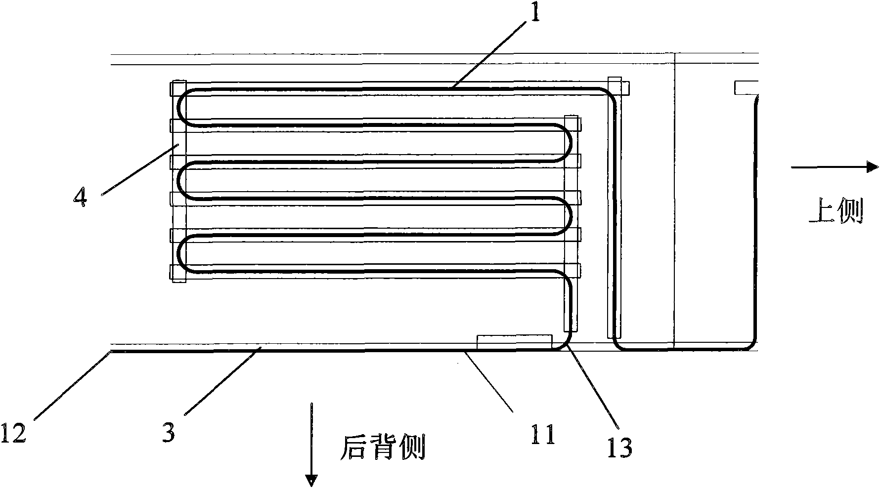
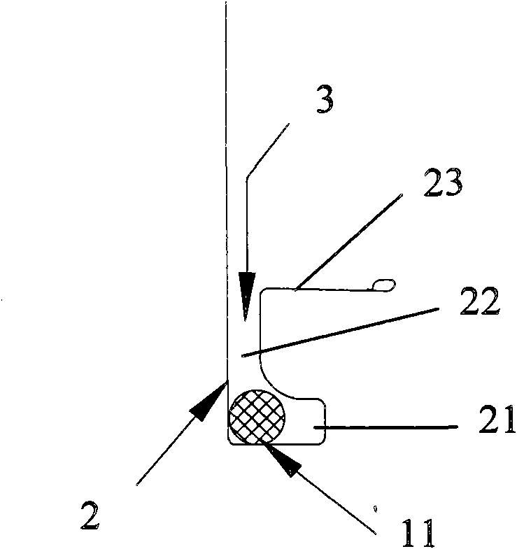
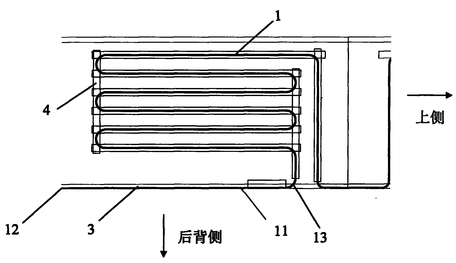
[0027] figure 1 The middle right side is the upper side of the refrigerator case, figure 1 The middle and lower side is the back side of the refrigerator box shell. like figure 1 As shown in , the condenser 1 is a light tube structure, which is bent back and arranged in the refrigerator case 2 (refer to figure 2 . Commonly known as U shell, including the top plate and two side plates, in the shape of the letter U) the inner side of the side plate ( figure 1 The outer side of the paper surface), and fixed by aluminum foil 4.

[0028] On the rear side of the refrigerator case, along the vertical direction ( figure 1 middle, left and right direction) is formed with a back card slot 3, the first row of pipelines of the condenser 1 counted from the back side of the refrigerator, that is, the pipeline 11 of the initial section from the condenser inlet 12 to the firs...


PUM


Abstract

The invention provides a refrigerator condensator installation structure, which comprises a refrigerator housing (2) and a condensator (1) tightly attached to the inner side of the refrigerator housing, wherein a back clamping groove (3) is formed at the inner side of the refrigerator housing (2); and a pipeline (11) at the initial segment of the condensator (1) is inserted into the back clamping groove (3). Because the pipeline at the initial segment of the condensator (1) is directly in contact with three surfaces of the refrigerator housing basically, the heat transfer area of the pipeline at the initial segment for transferring heat to outside directly through the refrigerator housing is greatly increased; moreover, because both the pipeline at the initial segment and the refrigerator housing have higher coefficient of heat conductivity, the coefficient of heat conductivity of the pipeline at the initial segment to the outside is higher; and compared with a traditional lateral plate condensator, the heat dissipating capacity of the condensator to the outside is greatly increased.

Description

technical field [0001] The invention relates to a refrigerator condenser installation structure, in particular to a built-in refrigerator condenser installation structure. Background technique [0002] The common condensers of mechanical refrigerators are external condensers, squirrel cage condensers and built-in light tube condensers. [0003] The external condenser is exposed to the environment for a long time, and it is prone to rust and leakage of refrigerant after long-term use, resulting in poor or no cooling. At the same time, the external condenser is easy to accumulate dust, which increases the heat transfer resistance and leads to poor heat transfer effect. [0004] Although fins are added to the squirrel-cage condenser, the heat transfer space is narrow, and auxiliary electric energy is needed to drive the fan to achieve its heat transfer effect. This is at the expense of energy consumption, which violates the idea of ​​energy saving and low carbon. [0005] The...

Claims


Application Information

Patent Timeline
IPC IPC(8): F25D19/00F25B39/04
Inventor 梁海山刘健如陈炜王晓路
Owner HAIER GRP CORP
Why Eureka
Try Eureka