Outdoor illuminating device and illuminating method

a technology of outdoor illumination and illuminating device, which is applied in the direction of lighting and heating apparatus, light source combinations, and built-in power, etc., can solve the problems of disturbing the blue light and affecting the smooth traffic of pedestrians and passing vehicles. , to achieve the effect of reducing environmental load, reducing power consumption, and alleviating global warming

Inactive Publication Date: 2010-12-23
OSAKA PREFECTURE +1
View PDF7 Cites 32 Cited by
  • Summary
  • Abstract
  • Description
  • Claims
  • Application Information

AI Technical Summary

Benefits of technology

[0029]The present invention can cut back power consumption because of the light source using LEDs, and achieve reduction of a load on the environment such as to alleviate global warming by virtue of low thermal dissipation from the light source.
[0030]In addition, the invention can give expectations for the effect of crime deterrence since the main lighting unit and the area of its vicinity are clearly visible in “blue color” from distant locations, while the bright illumination in white color in the area generally vertically below the main lighting unit does not impede but facilitate smooth traffic of pedestrians and vehicles passing under the main lighting unit.
[0031]The invention can hence contribute to the environmental design for establishing safe and secure communities by way of providing these “blue color” illuminating devices in numbers of areas in the communities.

Problems solved by technology

With the outdoor illuminating device of the conventional structure, however, there exists a problem even when the illumination light is changed simply to “blue color” that the solid blue color illuminated from the main lighting unit tends to produce uneven contrast of color tone on the ordinary road surface paved with asphalt, etc. of dark color, which has a contradicting effect of impeding the smooth traffic of pedestrians and passing vehicles in the area generally directly below the outdoor illuminating device.
There is also a problem when blue LEDs are mounted to the outdoor illuminating device of the conventional structure that it does not provide as much an effect of preventing crimes as anticipated since the directivity intrinsic to the LEDs is likely to cause color shading in certain directions of the illumination, which disturbs visually of the blue light for the pedestrians and passing vehicles at distant locations.

Method used


Image

  • Outdoor illuminating device and illuminating method
  • Outdoor illuminating device and illuminating method
  • Outdoor illuminating device and illuminating method

Examples


Embodiment Construction

[0053]Description is provided hereinafter of the preferred modes for carrying out the present invention.

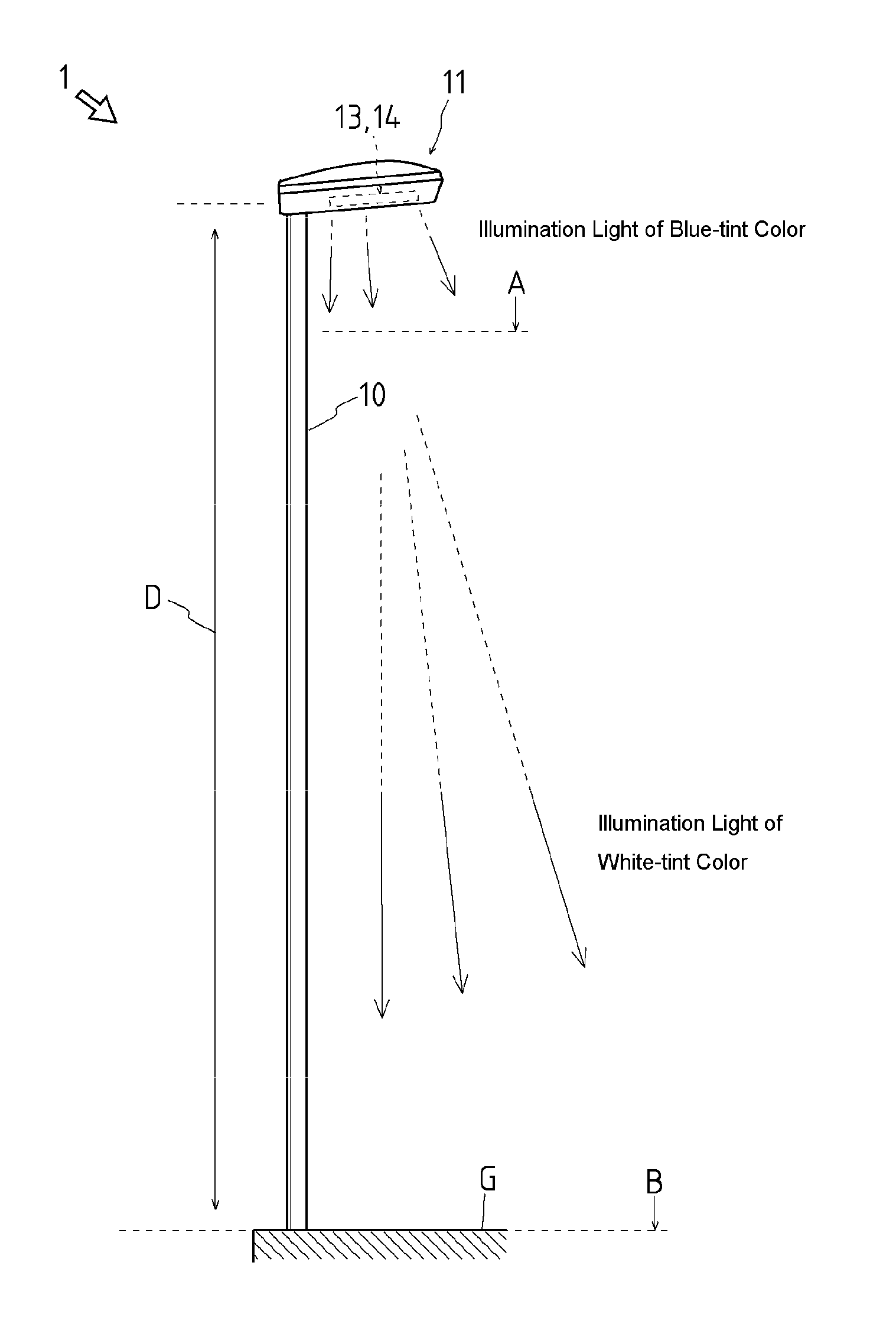
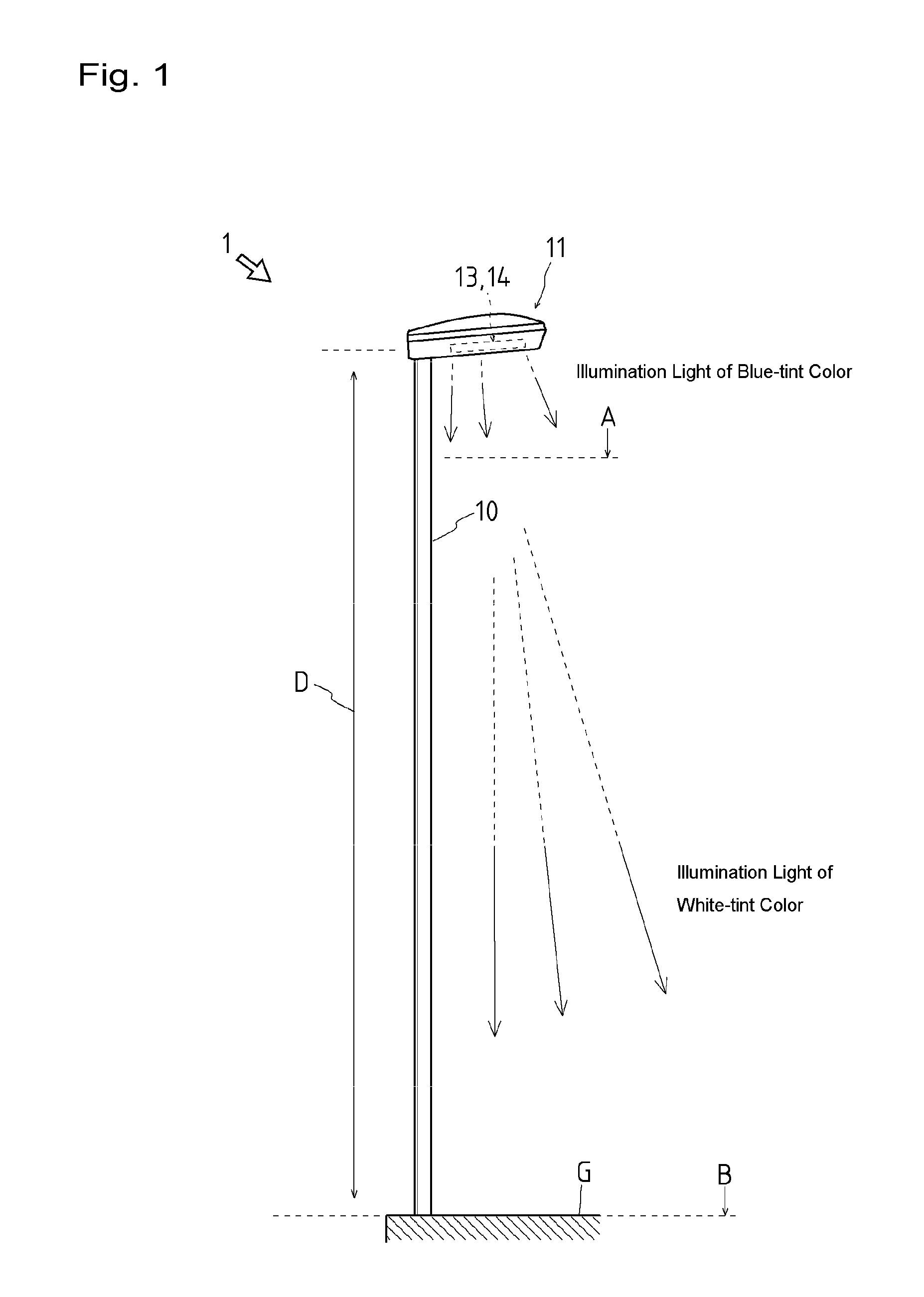
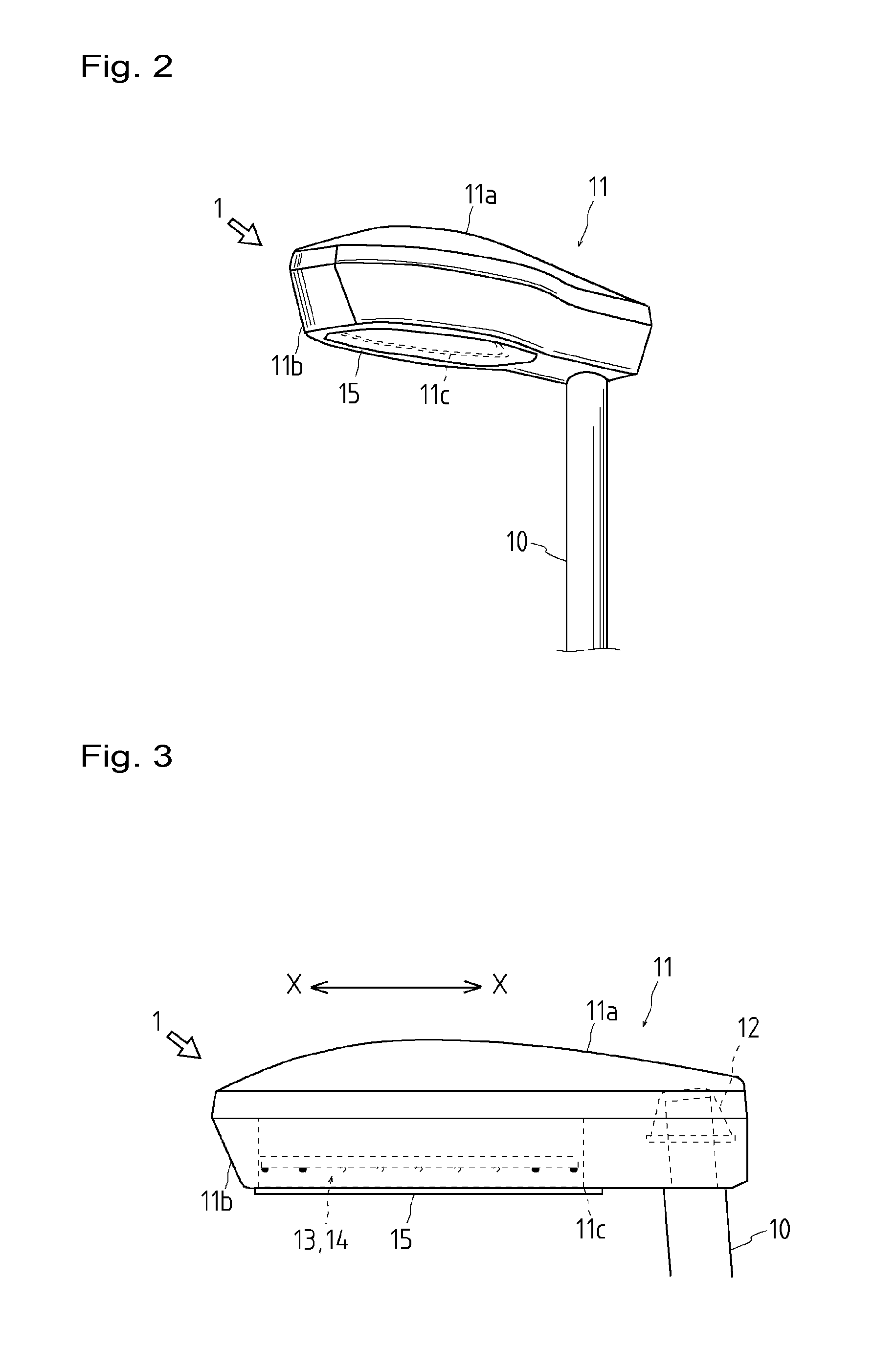
[0054]FIG. 1 is a side view depicting an overall structure of a security light according to one exemplary embodiment of the invention, FIG. 2 a perspective view of a main lighting unit, FIG. 3 a side view of the main lighting unit, FIG. 4 a bottom view of the main lighting unit, FIG. 5 another bottom view of the main lighting unit shown in FIG. 4, FIG. 6 illuminance distribution maps in the horizontal plane of illumination light emitted from the main lighting unit, FIG. 7 imaginary distribution maps of illumination light emitted from the main lighting unit, FIG. 8 a side view depicting a main lighting unit of a security light according to another exemplary embodiment, FIG. 9 another side view of the main lighting unit shown in FIG. 8, FIG. 10 a sectioned front view of the main lighting unit shown in FIG. 8, FIG. 11 a side view depicting an overall structure of a two-in-one street ...


PUM


Abstract

An outdoor illuminating device and illuminating method using LEDs as light sources to reduce a load on the environment and effectively function as a crime deterrent to contribute to environmental design for establishing safe and secure communities. Security light (1) capable of simultaneously emitting at least two different colors of illumination light is provided with a plurality of white LEDs (16) and blue LEDs (18) as the light sources. The security light (1) comprises main lighting unit (11) positioned at a predetermined distance (D) above the ground surface (G), first illuminating part (13) for emitting illumination light of white-tint color downward in the direction substantially vertical from main lighting unit (11), and second illuminating part (14) for emitting illumination light of blue-tint color to the outside of the area substantially vertically below main lighting unit (11).

Description

TECHNICAL FIELD[0001]The present invention relates to an outdoor illuminating device and an illuminating method, and more particularly to techniques pertaining to the outdoor illuminating device and the illuminating method capable of simultaneously emitting at least two different colors of illumination light and suitable for use as a street light, security light, and the like.BACKGROUND ART[0002]Streets and intersections in urban areas, parking lots, parks and the like spaces are provided with outdoor illuminating devices such as street lights and security lights. While incandescent lamps, mercury-vapor lamps, fluorescent lamps and the like kinds have hitherto been used as the light sources of the outdoor illuminating devices, there is a rise of numerous ideas in recent years of illuminating devices using LEDs (“Light Emitting Diodes”) as the new light sources that replace the incandescent and the other conventional lamps.[0003]Patent reference 1 discloses, as an example, an illumin...

Claims


Application Information

Patent Timeline
Patent Type & Authority Applications(United States)
IPC IPC(8): F21L4/02F21V9/00
CPCF21S8/086F21Y2101/02F21W2131/103F21S9/03F21Y2113/13F21Y2115/10Y02B20/72
Inventor WATANABE, KYOZOOKADA, HIROSHIHIRA, SHINJINAGATOME, KIMIAKI
Owner OSAKA PREFECTURE
Why Eureka
Try Eureka