Pipe punching bending device

A tube bending device and arc technology, applied in metal processing equipment, forming tools, manufacturing tools, etc., can solve problems such as difficulty in controlling the bending angle and strength, squeezing of the lumen channel, and inability to use it normally, achieving easy operation. Effect

Inactive Publication Date: 2018-04-20
湖南长宏南雁锅炉修理安装有限公司
View PDF10 Cites 3 Cited by
  • Summary
  • Abstract
  • Description
  • Claims
  • Application Information

AI Technical Summary

Problems solved by technology

[0003] The purpose of the present invention is to overcome the deficiencies of the prior art, and provide a stamping pipe bending device, which solves the problem that it is difficult to control the bending angle and strength of the traditional manual bending of steel pipes, and it is easy to cause the passage in the pipe cavity to be squeezed and cannot be bent. Problems with normal use

Method used


Image

  • Pipe punching bending device
  • Pipe punching bending device

Examples


Embodiment 1

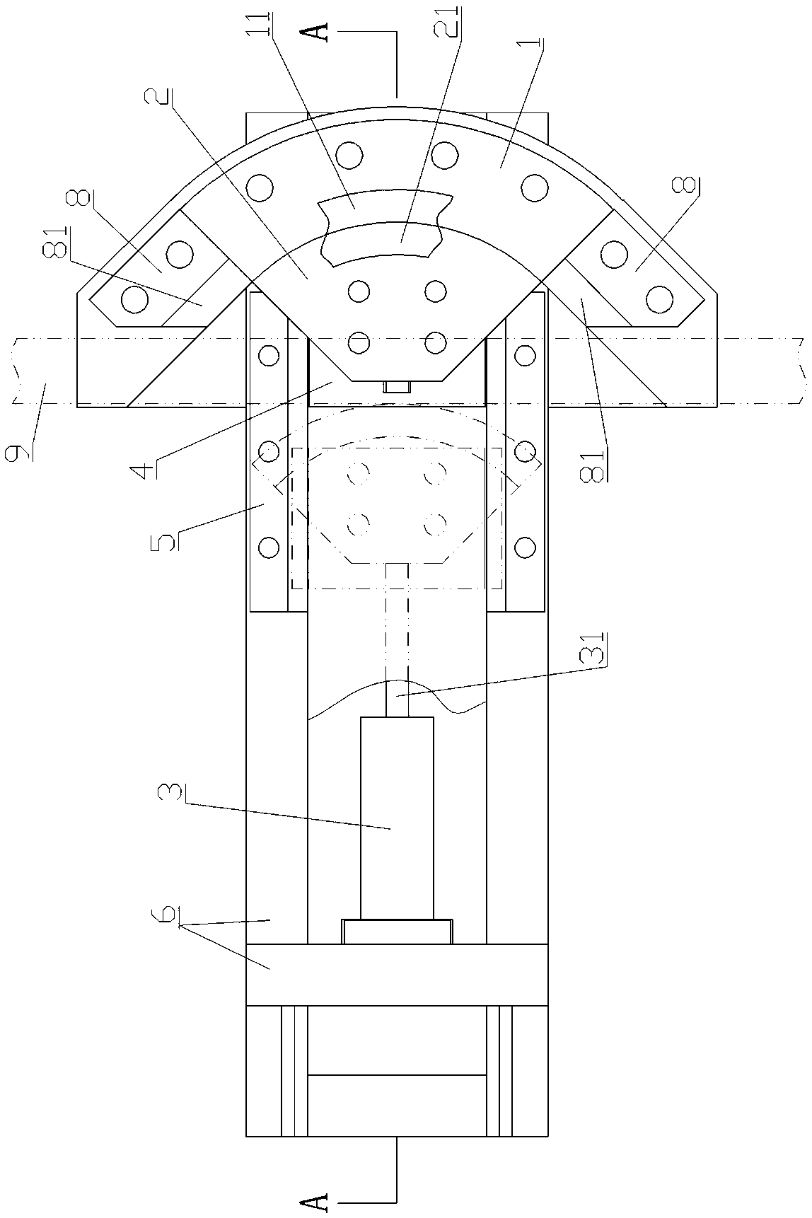
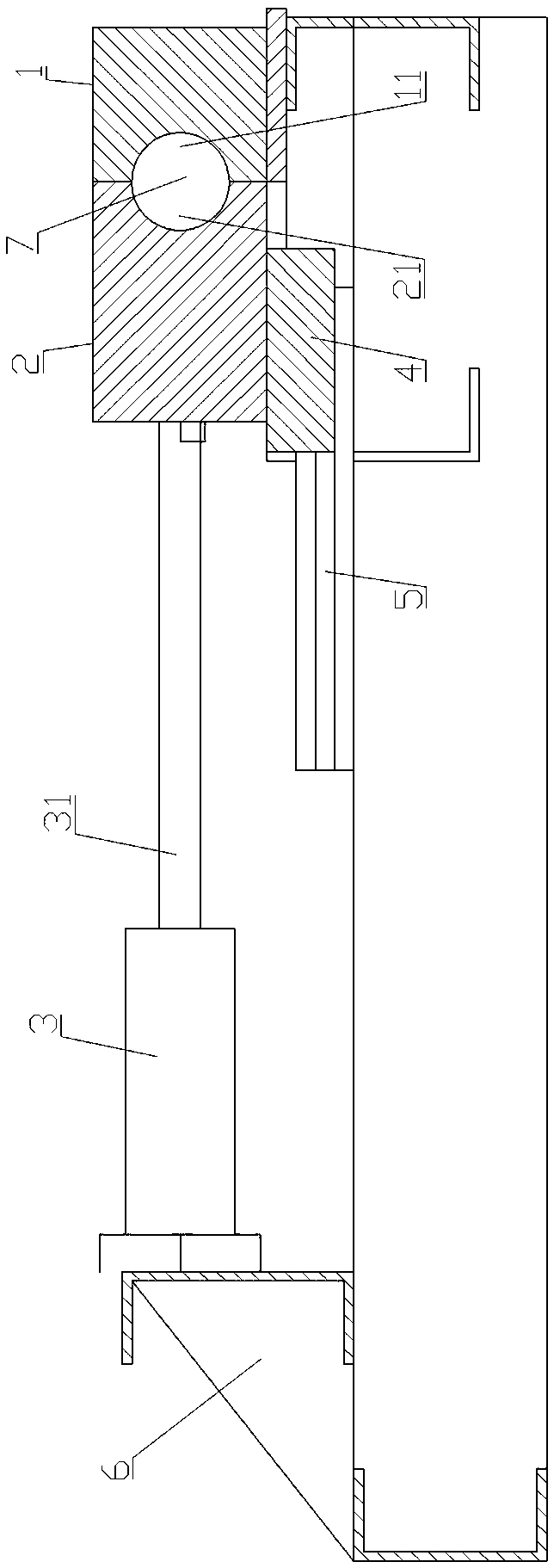
[0017] like figure 1 , 2 As shown, the stamping pipe bending device includes an arc outer mold 1, an arc inner mold 2, a jack 3, a slider 4, a slide rail 5 and a support 6.

[0018] The arc outer mold 1 is fan-cylindrical, and its lower end surface is fixedly connected on the support 6, and its inner arc surface is provided with a concave arc-shaped groove B11; the arc inner mold 2 is fan-cylindrical, and its lower end surface Fixed on the slide block 4, the outer arc surface is provided with a concave arc groove A21, the arc groove A21 is facing the arc groove B11 of the arc outer mold 1, and the other arc groove opposite to the outer arc surface One end face is the piston rod connection surface 22; the jack 3 is fixedly connected to the support 6, and its piston rod 31 extends horizontally and is connected to the piston rod connection surface 22 of the arc inner mold 2; the slider 4 is movably installed on the on the slide rail 5; the slide rail 5 is fixedly installed on t...


PUM


Abstract

A pipe punching bending device comprises a circular arc external mold, a circular arc internal mold, a jack, a sliding block, a sliding rail and a support base; the circular arc external mold is in sectorial cylinder shape, and the lower end face of the circular arc external mold is fixedly connected to the support base; the circular arc internal mold is in the sectorial cylinder shape, and the lower end face of the circular arc internal mold is fixedly connected to the sliding block; the jack is fixedly connected to the support base, and a piston rod of the jack extends out horizontally, andis connected to the connection surface of a piston rod in the circular arc external mold; the sliding block is movably installed on the sliding rail; the sliding rail is fixedly installed on the support base; and when the circular arc internal mold moves and comes into contact with the circular arc external mold, an arc-shaped groove A of the circular arc internal mold and an arc-shaped groove B of the circular arc external mold are spliced and combined to form a steel tube setting cavity. The pipe punching bending device provided by the invention has the advantages that the jack is started tomake the circular arc external mold and the circular arc internal mold combined, so that the bending of a straight steel tube can be achieved, and the operation is easy. In the press bending process,the arc-shaped groove A of the circular arc internal mold and the arc-shaped groove B of the circular arc external mold come into full contact with the outer wall of the straight steel tube, and thephenomenon that the bending part is flattened locally due to uneven stress is prevented effectively.

Description

technical field [0001] The invention relates to the technical field of bending machinery, in particular to a punching and bending device. Background technique [0002] In the production of steel pipe enterprises, steel pipe bending equipment is a commonly used equipment. Its function is to bend the steel pipe into a certain degree of curvature according to the needs of use. The existing bending mechanisms generally have complex structures and long production cycles. Defects. The traditional bending method is manual bending. This method is difficult to control the bending angle and strength. It is labor-intensive and time-consuming, and the accuracy is very low. It is often difficult to meet the requirements of use; The tube wall of the tube is severely deformed under compression, and the force is uneven, which causes the channel in the tube cavity to be squeezed flat and cannot be used normally. Contents of the invention [0003] The purpose of the present invention is t...

Claims


Application Information

Patent Timeline
Patent Type & Authority Applications(China)
IPC IPC(8): B21D7/06B21D37/10
CPCB21D7/06B21D37/10
Inventor 曹希新周跃兵王芳顺
Owner 湖南长宏南雁锅炉修理安装有限公司
Why Eureka
Try Eureka